1
Functional Fault Model for Micro Operation Faults
of High Correlation with Stuck-At Faults
Chia Yee OOI#1, Hideo FUJIWARA*2
#Microelectronics and Computer Engineering Department Universiti Teknologi Malaysia
81310 UTM Skudai, Johor, Malaysia
*Nara Institute of Science and Technology 8916-5 Takayama, Ikoma, Nara 630-0192, Japan
Abstract—Several functional fault models have been introduced and few of them have been shown to have high correlation with stuck-at fault model through experiment. However, not all the stuck-at faults are considered in the experiment. One of the fault categories which were out of consideration is stuck-at faults in the arithmetic modules. This is because there is no functional fault model correlating well with stuck-at faults in the arithmetic modules. In this work, we refine the functional fault model for arithmetic operations and show the superiority of our extended functional fault model to other functional fault model theoretically and experimentally.
Keywords
—
functional fault model, fault coverage, arithmetic operations.I. INTRODUCTION AND RELATED WORKS
The advances of the semiconductor technology have enabled the scaling deep into nanometer regime but manufacturing processes become more defect-prone. Besides improving the manufacturing equipment and its set-up, testing plays an important role to maintain the product quality under the constraint of time-to-market. Therefore, it is essential to control the quality and the size of test data as well as the time taken to generate the test data. Conventionally, test vectors are generated from a gate level netlist using a test generation tool. However, gate level test generation process has become more time consuming and complicated due to the increasing size and complexity of digital designs. Subsequently, some attempts have been done to perform the test generation process at high level of abstraction of the digital design, which can reduce test generation time because number of elements to be dealt with by the search process of test generation is much less.
Hierarchical test generation [1-3] is one of the high level test generation techniques. It involves test plan generation to deliver the precomputed test vectors to a module-under-test and to send the test responses to a primary output. The fault model used is stuck-at fault model. However, the limitation of this test generation technique is that the test quality of the precomputed test vectors mainly depends on the synthesis library eventually used in the gate-level synthesis. The fault coverage is not guaranteed if the precomputed tests vectors
are not dedicated to the selected component from the synthesis library.
Another high level test generation technique is called functional test generation, which is independent of the synthesis library. However, stuck-at fault model is improper at this abstraction level. Thus, functional fault models [4-8] have been introduced to support the high level test generation platform. Functional fault model has been introduced in [4] for multiplexers. They showed that the fault model has improved the accuracy of high level test generation. In addition, some functional fault models [5-6] were introduced for finite state machine only. More complete functional fault models which can represent failure at more syntax of HDL description are Fummi’s fault model[7] and Chen’s fault model[8]. The models are detailed in the following text. A. Fummi’s Fault Model
Fummi et. al [7] introduced a fault model that consists of the following:
i. Bit failure – each variable, signal or port is considered as a vector of bits. Each bit can be stuck-at zero or one.
ii. Condition failure – each condition can be stuck-at true or stuck-at false, thus removing some execution paths in the erroneous HDL description. B. Chen’s Fault Model
Chen et. al [8] defined a fault model that include the following ten faulty cases:
i. Input stuck-at fault - a failure of the primary input signal that can be stuck at 0 or 1.
ii. Output stuck-at fault - a failure of the primary output signal that can be stuck at 0 or 1.
iii. If stuck then fault - a failure to execute the else portion of the statements for the if construct. iv. If stuck else fault - a failure to execute the if portion
of the statements for the if construct.
v. Assignment statement fault - a failure to assign a new correct value to a signal.
vi. Dead clause fault - a failure of a case statement to execute when selected.
vii. Micro-operation fault - a failure of micro-operation to perform its intended function. The operators for
11th IEEE Workshop on RTL and High Level Testing (WRTLT'10), pp. 139-144, Dec. 2010.
2
the micro-operation can be logical operators, relational operators, unary operators, and arithmetic operators.
viii. Local stuck data fault - a failure for a signal object to have a proper value within a local expression. Chen’s fault model has an advantage over Fummi’s fault model because it can represent more stuck-at faults. Chen’s fault model for micro operation faults can cover some stuck-at faults in the arithmetic operators like adder, and subtractor, etc. It also covers stuck-at faults in both relational operators and logical operators. Local stuck data faults represented by Chen’s fault model can cover stuck-at faults which appear at fan-out branches besides fan-out stem. This paper first studies the correlation between the micro operation fault of Chen’s fault model with the stuck-at fault model. We also propose the extension for functional fault model in order to close the gap between the fault model and the stuck-at fault model.
II. CORRELATION BETWEEN CHEN’S FAULT MODEL AND
STUCK-AT FAULT MODEL
Micro operation fault represents a failure of an operator to perform its intended functions. The following example lists an addition operator and its faulty counterparts.
Example 1:
SUM <= A + B; ‐‐Good operation: addition SUM <= A – B; ‐‐Faulty operation 1: subtraction SUM <= A * B; ‐‐Faulty operation 2: multiplication SUM <= A / B; ‐‐Faulty operation 3: division SUM <= A % B; ‐‐Faulty operation 4: modulo
SUM, A and B can be vectors of bits. By modeling faults of the addition in this way, it might be too loose to correlate with many stuck-at faults at gate level. For instance, let SUM, A and B be 4-bit variables respectively. Test vector A=0001 and B=0001 can detect all faults listed in Example 1 (Faulty operations 1-4). However, this test vectors cannot cover many stuck-at faults at gate level. Thus, the gap between this functional fault model and stuck-at fault model is still big. In other words, the functional fault model contains little structural information to contribute to high fault coverage in test generation. Therefore, it is important to extend the fault model through model refining. We propose an extension for micro operation faults in arithmetic operations. This is detailed in the following section.
III. EXTENSION OF FAULT MODEL FOR MICRO OPERATION
FAULTS
We extend the fault model by considering that each micro operation functionally consists of W bit-slices where W is the bit-width of operation. The extended micro operation faults are called bit-slice micro operation fault. It represents a failure of a bit-slice of an operator to perform its intended functions.
A. Adjacent Bit-Slice Micro Operation Fault
Definition 1: Adjacent bit-slice micro operation fault is a failure of n bit-slices of the W-bit operator to perform its intended function where n ≤ W and W is the bit-width of the operation.
Definition 2: The fault list Fn of a W-bit operator with operation op is
: ’ : | ,
’
where A and B are the input of the operation. op is called an operation under test.
In the following text, we show that the size of the fault list does not grow tremendously with the size of the bit-width using the proposed fault model. Let w be the bit-width. The number of faults |Fi| in the fault model for adjacent bit-slice micro operation faults with n be the number of faulty adjacent bit-slices is as follows. N denotes the number of arithmetic operations.
|Fi|= Notes:
(w-n+1)=the number of faults for n bit-slice faulty micro operation.
(N-1)=the number of arithmetic operations other than the operation under test.
Example 2: The fault list Fn of a 4-bit addition (+) with a failure of two bit-slices is
: : , : : ,
: : , : : ,
: : , : : ,
: / : , : / : ,
: / : , : % : ,
: % : , : % :
where A and B are the input of the operation. The total number of faults is 12. Note that % represents a modulo operation.
Chen’s micro operation faults are covered by the adjacent bit-slice micro operation fault. It is equal to the adjacent bit- slice micro operation fault with n=W. Therefore, we can conclude that bit-slice micro operation faults are superior to Chen’s micro operation faults.
B. Array Micro Operation Fault
However, adjacent bit-slice micro operation is not sufficient to represent faults in complex combinational operators like multiplier, divider and modulo operator. This is because the logic of a bit-slice is not only dependent on the logic of adjacent bit slices. Therefore, we introduce another
3
fault model called array micro operation fault for these operators.
First, let addition, subtraction and logical operations be considered as basic operations while let multiplication, division and modulus be complex operations. Multiplication, division and modulo can be modeled in terms of basic operations. This model contains more structural information of a complex operator. Let A and B be the inputs of n-bit multiplication and C be the output. The operation can be modeled as an array multiplication as follows.
: , &
where is an n bits consisting of eight repeating bits of B[i] while i'b0 means i-bit 0s. Note that P i is n-bit too. By defining a micro operation fault for multiplication based on the multiplication model above, the fault is more refined and closer to the structural faults of a synthesized combinational multiplier.
Definition 3: Array micro operation fault is a failure of n bit- slices of a W-bit basic operator in a complex operation to perform its intended function where n ≤ W and W is the bit- width of the basic operation.
Using multiplication as an example, we show that the size of the fault list is still manageable and much smaller than the gate-level stuck-at fault size. Let w be the bit-width. The number of faults |Fi| in the fault model for array micro operation faults with n be the number of bits in a faulty adjacent bit-slices is as follows. Nj denotes the number of faulty operations of category j. Mj denotes the number of basic operators of category j that compose the multiplication. K denotes the number of operation categories involved. Note that the size of the fault list does not grow tremendously with the size of the bit-width using the proposed fault model.
|Fi|=∑
Example 3: In the array multiplication, it consists of two types of operations from different categories, i.e. addition of arithmetic category and AND operation of logical category. Therefore, K is 2, M1 and M2 represent the number of additions and AND operations, respectively.
Example 4: F0 and F1 are the fault lists for an array multiplication using the proposed array micro operation faults. F0 is the faults that involve addition while F1 is the faults that involve AND logic operation.
: ’ : | ’
, ’ ,
: , ’ ’ ’ ,
’ ,
Similarly, both division and modulo operation can be modelled in an array of basic operations.
IV. FAULTY MULTIPLICATION GENERATION COMPLEXITY
This section describes the pseudo code to generate faulty multiplications according to the given fault list based on our proposed fault models for adjacent bit-slice micro operation faults and array micro operation faults. These are shown as pseudo code. In our experiment, we will generate the faulty multiplication in constraint format for SystemVerilog language. The pseudo code can be referred for other formats too (C++, etc.).
Int W = 8 //W is the bitwidth
Char operation_type[5] = {+, -, /, %, *}//all operations For(op_num=0; op_num<4; op_num++) //bounded by #operations-1
For(bit_slice=1; bit_slice<=W; bit_slice++) For(int i=W-1; i>=bit_slice-1; i--)
{ Open file to store the constraint model Print file header
Print bit-slices with faulty operations Print bit-slices with good operations
Print the coding that generate the test vectors ………
Write the test pattern to STIL file if it does not exist in the STIL file
}
Figure 1 Pseudo code for generating adjacent bit-slice micro operation faults for multiplication without compaction
Figure 1 is the proposed coding to generate adjacent bit- slice micro operation faults for multiplication. There are three for loops that determine the time complexity of the algorithm to solve the problem. The first for loop is bounded by a fixed constant of 4 which is the number of operations under arithmetic category. The other two for loops are bounded by the bit-width; bit-slice in the second for loop is the number of bits of faulty adjacent bit-slices while i in the third for loop corresponds to the first bit position of the adjacent faulty bit- slices. Therefore, the time complexity for this algorithm is O(n2) where n is the size of the problem which is bit-width of multiplication under test.
To reduce the test patterns generated, we introduce an algorithm for bit-slice micro operation faults with compaction. The compaction is done by including maximum number of neighboring faults in a given fault list into the test generation model so that the test generation platform can generate just one test pattern to detect those faults. Figure 2 shows the pseudo code. It has two for loops that dominate the time complexity of generating adjacent bit slice micro operation faults with compaction. So, the complexity is O(n2) too. Note that bit_slice and i denote the same thing as in Figure 1.
Int W = 8 //W is the bitwidth
4
Char operation_type[5] = {+, -, /, %, *}//all types of operations
//PART 1: generate faults
For(op_num=0; op_num<4; op_num++) //bounded by #operations-1 For(bit_slice=1; bit_slice<=W; bit_slice++)
For(int i=W-1; i>=bit_slice-1; i--) {
Generate bit-slices with faulty operations Generate bit-slices with good operations
Update the number of functional faults as fcount }
//PART 2: generate and write pattern to a file }
Figure 2 Pseudo code for generating adjacent bit-slice micro operation faults for multiplication with compaction
Figure 3 shows the algorithm pseudo code for array micro operation faults with compaction. Part 1 (resp. Part 2) is to generate faults for basic operation of addition (resp. AND operation). There are three for loops which are bounded by bitwidth W both in Part 1 and Part 2. bit_slice and idenote the same things as in Figure 1. j means the number of basic operations, i.e. additions, in the array multiplication in Part 1 while k means the number of basic operations, i.e. AND logical operations, in the array multiplication. Therefore, the time complexity for this algorithm is O(n3) where n is the size of the problem, i.e. the bit-width of multiplication under test.
PART 1: Generating faults for addition Int W = 8 //W is the bitwidth
Char operation_type[5] = {*, -, /, %, +}//all operations For(op_num=0; op_num<4; op_num++) //bounded by #operations-1
For(bit_slice=1; bit_slice<=W; bit_slice++) For(int j=0; j<W-1; j++)
For(int i=W-1; i>=bit_slice-1; i--) { Open file to store the constraint model Print bit-slices with faulty operations Print bit-slices with good operations
Print the coding that generate the test vectors }
PART 2: Generating faults for AND logical operation
Char operation_type2[6] = {or, nor, nand, xor, xnor, and}//all operations
For(op_num=0; op_num<4; op_num++) //bounded by #operations-1 For(bit_slice=1; bit_slice<=W; bit_slice++)
For(int k=0; k<W; k++)
For(int i=W-1; i>=bit_slice-1; i--) { Open file to store the constraint model Print bit-slices with faulty operations Print bit-slices with good operations
Print the coding that generate the test vectors }
PART 3: Generating test patterns to a file
………
Figure 3 Pseudo code for generating array micro operation faults for multiplication with compaction
V. EXPERIMENT SETUP AND RESULTS
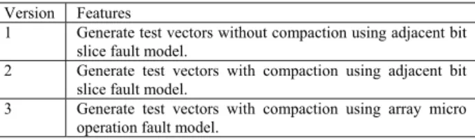
Several arithmetic operations were used to evaluate the accuracy of the fault model proposed. These include addition, subtraction, multiplication and division. Table I summarize three different fault generation programs to be used to generate test vectors.
TABLEI
THREE VERSIONS OF FAULT GENERATION PROGRAMS Version Features
1 Generate test vectors without compaction using adjacent bit slice fault model.
2 Generate test vectors with compaction using adjacent bit slice fault model.
3 Generate test vectors with compaction using array micro operation fault model.
To evaluate the correlation between the proposed extended fault model and the stuck-at fault model, an experiment as shown in Figure 4 is set up. Besides showing that the new functional fault model contributes to high fault coverage, we also showed that this can be achieved with short test length which is comparable to the one from gate level test generation. Table II shows the test length in the third column with also the number of gate-level stuck-at faults in the second column when gate-level test generation is performed.
Figure 4 Experiment Flow
TABLEII
TOTAL NUMBER OF FAULTS AND TEST APPLICATION TIME FOR 100%FAULT EFFICIENCY
Operator #faults Test length (100%) 8-bit Adder 394 13 8-bit Subtractor 426 11 8-bit Multiplier 1670 35 8-bit Divider 2218 68
In Table III, n in the first column denotes the number of bits in the faulty slices while #F.fault denotes the number of functional faults. FTG(s) indicates the computation time to generate the test patterns in seconds. FC(%) means fault coverage in percentage and TL means test length in clock cycles (CCs). First, we compare the fault coverage resulted
Adjacent bit-slice micro operation faults for an operation under test
Functional test generation with/without compaction
Fault simulation of the operator under array /random logic implementation.
Fault coverage and test length evaluation
Array micro operation fault for an operation under test
Functional test generation with compaction
Fault simulation of the operator under array /random logic implementation.
5
from our proposed functional fault model with Chen’s fault model. The row of n=8 in Table III for adjacent bit-slice micro operation fault model represents the experimental result of Chen’s fault model. The fault coverage is not the highest compared to that of the fault model when n<8. This means micro operation faults from Chen’s fault model alone is not sufficient to obtain high fault coverage. The average fault coverage for any n for addition, subtraction and multiplication using adjacent bit-slice micro operation fault model is above 65%. However, the fault coverage is not good for division under the same fault model. Thus, the division fault coverage was evaluated again using array micro operation fault model. It showed a tremendous improvement as can be seen from the last two column of Table III. This means some complex operation like division needs more refined fault model to obtain more accurate fault coverage. Besides fault coverage, test length from our proposed functional fault model was evaluated. Test length could be reduced for 2~3 times if the functional test generation is equipped with compaction technique though the compaction caused the increase of computation time of functional test generation for 2 times.
To show further the evaluation of our functional fault model in fault coverage and test length, we proposed two methods of fault simulation at gate-level given the test patterns from the functional test generation using our proposed functional fault models. These methods are fault simulation with linear ordering of n and fault simulation with binary ordering of n, where n is the number of bits of faulty adjacent slices in the extended micro operation faults. In the first fault simulation, fault simulation starts with the functional faults of n-bit faulty adjacent bit-slices where n is in increasing order, i.e. n=1,2,3,…. until the required minimum fault coverage is achieved (e.g. 98%). The second fault simulation requires n to proceed with binary ordering, i.e. , , , , , , , . The experimental result of these two fault simulations are tabulated in Table IV. In this part of the experiment, we use adjacent bit-slice micro operation fault model for addition, subtraction and multiplication and array micro operation fault model for division. The functional test generation performed here are with compaction. Although Table III shows that the fault coverage from test generation with compaction is generally lower than that from test generation without
compaction, the test patterns from the former can achieve 100% for addition and subtraction with short test length, 20~26 and 28~29, respectively. Fault simulation with linear ordering of n showed better result in term of test length over fault simulation with binary ordering of n for both addition and subtraction. High fault coverage was also obtained for multiplication and division, which are 99.64% and 90.20%, respectively.
VI. CONCLUSION
We have proposed a more accurate functional fault model for micro operations to be used in high level test generation platform. This could close the gap of test data quality between functional test generation and gate-level test generation as reflected by the high fault coverage obtained in the experiment. The proposed functional fault model will be used to evaluate the fault coverage and test application time for sequential circuits without scan. Besides arithmetic operations, similar extension should be studied for relational operations.
REFERENCES
[1] T. M. Sarfet, R.G. Markgraf, M.H. Schulz and E. Trischler, “A hierarchical test pattern generation system based on high-level primitives,” IEEE Trans. on CAD and Integrated Circuits and Systems, vol. 11, pp. 34-44, 1992.
[2] J. Lee and J. H. Patel, “Hierarchical test generation under architectural level functional constraints,” IEEE Trans. on CAD and Integrated Circuits and Systems, vol. 15, pp. 1144-1151, Sept. 1996.
[3] I. Ghosh and M. Fujita, “Automatic test pattern generation for functional register-transfer level circuits using assignment decision diagrams,” IEEE Trans. on CAD and Integrated Circuits and Systems, vol. 20, pp. 402-415, 2001.
[4] Jaan Raik and Raimund Ubar, “Enhancing hierarchical ATPG with a functional fault model for multiplexers,” Proceeding of DDECS, pp. 219-222, 2004.
[5] K.T. Cheng and J.Y. Jou, “A functional fault model for sequential machines,” IEEE Trans. Of Comp. Aided Des. Of Int. Circuits Sys, pp. 1065-1073, September 1992.
[6] I. Pomeranz, S. Patil and P.K. Parvathala, “A functional fault model with implicit fault effect propagation requirements,” Proceeding of ATS, pp. 95-102, 2006.
[7] F. Ferrandi, F. Fummi and D. Sciuto, “Implicit Test Generation for Behavioral VHDL Models,” Proc. of the Int. Test Conf., pp. 587, 1998. [8] C-I. H. Chen, “Behavioral test generation/fault simulation”, IEEE
Potentials, pp. 27-32, Feb/Mac 2003.
6
TABLEIII
TEST GENERATION WITH AND WITHOUT COMPACTION USING EXTENDED MICRO OPERATION FAULT MODEL
op n ADJACENT BIT-SLICE MICRO OPERATION FAULT MODEL ARRAY MICRO OPERATION FAULT MODEL
#F. fault No compaction With compaction #F. fault With compaction
FTG (s) FC (%) TL (CCs) FTG (s) FC (%) TL (CCs) FTG (s) FC (%) TL (CCs)
addition
1 32 147.71 95.94 18 261.02 94.16 9
2 28 100.30 95.43 17 219.01 77.16 6
3 24 99.62 94.67 16 213.22 84.01 5
4 20 84.53 91.37 17 149.55 80.20 5
5 16 66.73 90.36 11 125.21 82.23 5
6 12 51.62 82.74 9 91.96 73.10 4
7 8 28.61 74.62 6 51.26 53.30 2
8 4 16.95 75.13 4 18.61 35.03 1
subtraction
1 32 135.08 95.77 16 323.94 90.38 9
2 28 126.79 95.54 15 269.56 88.26 7
3 24 124.92 95.07 21 233.34 83.33 6
4 20 99.48 95.07 19 177.06 91.55 6
5 16 80.37 87.56 12 162.07 84.27 6
6 12 87.98 85.45 9 110.71 73.24 4
7 8 35.98 74.18 4 70.12 71.83 3
8 4 20.81 72.54 4 24.53 39.20 1
multiplication
1 32 51.79 85.75 16 180.06 94.01 15 544 6248.03 94.97 90
2 28 44.80 88.68 17 140.94 86.71 11 476 4940.62 95.09 79
3 24 38.64 74.55 15 102.43 82.04 7 408 4685.85 95.03 64
4 20 32.14 84.97 11 80.21 75.33 5 340 3917.01 94.73 68
5 16 26.23 76.89 11 58.29 69.10 4 272 3029.00 94.91 52
6 12 19.09 69.10 9 39.75 51.26 2 204 1984.90 94.85 40
7 8 12.80 57.96 5 26.45 44.67 2 136 1430.28 94.73 35
8 4 7.46 73.71 4 6.90 32.87 1 68 403.67 34.13 2
division
1 32 161.90 34.28 23 283.53 24.16 7 272 2822.24 70.05 50
2 28 131.67 34.06 22 230.84 16.40 6 240 2402.06 74.16 41
3 24 133.16 17.48 18 212.90 33.92 6 208 2105.73 74.30 40
4 20 102.60 23.22 15 187.95 15.99 5 176 1724.97 74.89 37
5 16 78.71 19.33 14 136.35 8.08 5 144 1368.68 71.77 33
6 12 57.93 20.55 8 110.42 7.09 4 112 1115.55 69.83 26
7 8 44.99 16.44 6 67.60 6.01 3 80 753.13 56.96 17
7
TABLEV
OPTIMIZED TEST LENGTH USING FAULT SIMULATIONS WITH LINEAR ORDERING AND BINARY ORDERING op Fault simulation with linear ordering of n Fault simulation with binary ordering of n
n # F. fault
FTG (s) FC (%) TL (CCs)
n # F.
fault
FTG (s) FC (%) TL (CCs)
addition
≤1 32 261.02 94.16 9 8 4 18.61 35.03 1
≤2 60 480.03 98.73 15 8,4 24 168.16 81.22 6
≤3 84 693.25 100 20 8,4,2 52 387.17 94.16 12
≤4 8,4,2,1 84 648.19 99.75 21
≤5 8,4,2,1,3 108 861.41 100 26
≤6 8,4,2,1,3,6
≤7 8,4,2,1,3,6,5
≤8 8,4,2,1,3,6,5,7
subtraction
≤1 32 593.5 90.38 9 8 4 24.53 39.20 1
≤2 60 826.84 96.24 16 8,4 24 201.59 91.78 7
≤3 84 1003.9 97.89 22 8,4,2 52 471.15 98.83 14
≤4 104 1165.97 100 28 8,4,2,1 84 795.09 99.77 23
≤5 8,4,2,1,3 108 1028.43 100 29
≤6 8,4,2,1,3,6
≤7 8,4,2,1,3,6,5
≤8 8,4,2,1,3,6,5,7
multiplication
≤1 32 180.06 94.01 15 8 4 6.90 32.87 1
≤2 60 321.00 97.25 26 8,4 24 87.11 79.58 6
≤3 84 423.43 99.34 33 8,4,2 52 228.05 91.08 17
≤4 104 503.64 99.34 38 8,4,2,1 84 408.11 97.54 32
≤5 120 561.93 99.40 42 8,4,2,1,3 108 510.54 99.58 39
≤6 132 601.68 99.40 44 8,4,2,1,3,6 120 550.29 99.58 41
≤7 140 628.13 99.40 46 8,4,2,1,3,6,5 136 608.58 99.64 45
≤8 144 635.03 99.64 47 8,4,2,1,3,6,5,7 144 635.03 99.64 47
division
≤1 272 2822.24 70.05 50 8 48 408.17 58.45 9
≤2 512 5224.3 80.22 91 8,4 224 2133.14 76.38 46
≤3 720 7330.03 84.96 131 8,4,2 464 4535.2 82.38 87
≤4 896 9055.00 86.90 168 8,4,2,1 736 7357.44 83.97 137
≤5 1040 10423.68 89.43 201 8,4,2,1,3 944 9463.17 86.90 177
≤6 1152 11539.23 90.20 227 8,4,2,1,3,6 1056 10578.72 88.62 203
≤7 1232 12292.36 90.20 244 8,4,2,1,3,6,5 1200 11947.4 90.20 236
≤8 1280 12700.53 90.20 253 8,4,2,1,3,6,5,7 1280 12700.53 90.20 253