Constraint-Based Hierarchical Untestability
Identification for Synchronous Sequential Circuits
Jaan Raik, Anna Rannaste, Maksim Jenihhin, Taavi Viilukas, Raimund Ubar
Department of Computer Engineering Tallinn University of Technology, Estonia
E–mail: [email protected]
Hideo Fujiwara
Graduate School of Information Science, Nara Institute of Science and Technology
Kansai Science City, 630–0192, Japan E–mail: [email protected]
Abstract— The paper proposes a new hierarchical untestable stuck-at fault identification method for non-scan sequential circuits containing feedback loops. The method is based on deriving, minimizing and solving test path activation constraints for modules embedded into Register-Transfer Level (RTL) designs. First, an RTL test pattern generator is applied in order to extract the set of all possible test path activation constraints for a module under test. Then, the constraints are minimized and a constraint-driven deterministic test pattern generator is run providing hierarchical test generation and untestability proof in sequential circuits. We show by experiments that the tool is capable of quickly proving a large number of untestable faults obtaining high fault efficiency. As a side effect, our study shows that traditional bottom-up test generation based on symbolic test environment generation at RTL is too optimistic due to the fact that propagation constraints are ignored.
I. INTRODUCTION
Test generation for sequential synchronous designs is a time-consuming task. Automated Test Pattern Generation (ATPG) tools spend a lot of effort not only for deriving test vectors for testable faults but also for proving that there exist no tests for the untestable faults. Because of this reason, the identification of untestable faults has been an important aspect in speeding up the sequential ATPG.
For combinational circuits, untestable faults occur due to the redundant logic in the circuit, while for sequential circuits, untestable faults (i.e. sequentially untestable faults) may also result due to unreachable states or due to impossible state transitions. A number of works have been proposed in order to tackle the problem of identifying sequentially untestable faults. The first methods [1] were fault-oriented and based on applying combinational ATPG to the expanded time-frame model of the sequential circuit. However, such approach does not scale because of the size-explosion of the unrolled
identification. However, it was shown in [4] that this method may result in ‘false positives’, i.e. a fault may be declared untestable when there actually exists a test for it. The common limitation of the above methods is that they operate at the logic-level representation of the design. Thus a considerable amount of effort is put on the implication process carried out at the level of logic netlists.
In their previous work [6], the authors introduced a specific subclass of sequentially untestable faults, called register enable stuck-on faults and a method for proving them untestable using a model checker. In this paper we propose a hierarchical untestability identification method. The new method allows detecting sequential untestability in combinational modules (functional units, multiplexers) embedded into a hierarchical circuit and is based on path activation constraints extracted by a Register-Transfer Level (RTL) ATPG.
In hierarchical RTL test generation, top-down and bottom- up strategies are known. In the bottom-up approach, tests generated at the low-level will be later assembled at the higher abstraction level. Such algorithms yield short run-times but ignore the incompleteness problem: constraints imposed by other modules and/or the network structure may prevent test vectors from being assembled. In the top-down approach, constraints are extracted at the higher level as a goal to be considered when deriving tests for modules at the lower level. This approach allows testing modules embedded deep into the RTL structure. However, as modules are often tested through highly complex constraints, their fault coverage may be compromised.
Early methods on bottom-up RTL testing relied on the assembly of module tests and were applicable of the simplest systems only [7]. A more solid basis for the bottom-up paradigm was laid by Ghosh et al. in [8]. In their work, test environments are generated for each functional module of a Sixteenth IEEE European Test Symposium
generate the test environments. To overcome this drawback, Zhang et al. upgraded the nine-valued algebra to a ten-valued algebra by taking the signal line value range into consideration. This algebra is able to generate much more test environments [10]. In [11], Zhang’s approach has been further improved by introducing additional propagation rules.
Lee and Patel introduced top-down constraint-based test pattern generation for microprocessors in [12]. Several constraint-based top-down approaches followed, including [13, 14]. [15] proposed a bottom-up approach based on a High- Level Decision Diagram (HLDD) engine and a commercial SICStus constraint solver. As experiments show, the tool achieves lower fault coverage in comparison to a commercial logic-level Automated Test Pattern Generator (ATPG). In [16], a top-down approach including a constraint solving package ECLiPSe [17] has been proposed.
None of the previous methods apply RTL constraints in order to prove logic-level untestable faults. Thus, the fault efficiency reported by the approaches [12-16] is often low, which decreases the test engineer’s confidence in the test. (Fault efficiency refers to the ratio of the number of tested faults to the number of testable faults). In addition, as we will show in this paper, in many cases, fault coverage obtained for the modules in RTL test generation may considerably decrease if path activation constraints are being ignored.
In this paper we propose a new hierarchical untestability identification method for non-scan sequential circuits containing feedback loops. To the best of our knowledge this is the first method that can prove sequentially untestable stuck-at faults starting from the RTL. The method is based on deriving, minimizing and solving test path constraints for modules embedded into RTL designs. First, an RTL test pattern generator is applied in order to extract the set of all possible test path activation constraints for a module under test within a certain clock cycle limit. Then, the constraints are minimized and a constraint-driven deterministic test pattern generator is run providing a time-limit-bounded hierarchical test generation and untestability proof for sequential circuits. We show by experiments that the tool is capable of quickly proving a large number of untestable faults obtaining high fault efficiency. As a side effect, our study shows that traditional bottom-up test generation based on symbolic test environment generation at RTL is too optimistic due to the fact that propagation constraints are ignored.
The paper is organized as follows. Section 2 presents the definition of ADD models, which is used as the basis of presenting the untestability identification method. In Section 3, the new untestability indentification setup is presented and a motivating example showing the limitations of existing bottom-up approaches is presented. Section 4 explains the process of obtaining the set of RTL constraints for proving sequential untestability. Section 5 discusses the core benefits of the proposed method. Section 6 provides experimental results. The paper ends with Conclusions.
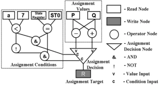
II. TEST ENVIRONMENT GENERATION WITH ADDS Assignment decision diagram (ADD) [9] is an acyclic graph that consists of a set of nodes that can be categorized into four types: read node, write node, operation node and assignment decision node (ADN), and a set of edges which contain the connectivity information between two nodes (Figure 1). A read node represents a primary input port, a storage unit or a constant while a write node represents a primary output port or a storage unit. An operation node expresses an arithmetic operation unit or a logic operation unit while an ADN selects a value from a set of values that are provided to it based on the conditions computed by the logic operation units. If one of the condition inputs becomes true, the value of the corresponding data input will be selected.
Figure 1. Assignment Decision Diagram (ADD)
When a node N is under test, the testability of the node is guaranteed if (a) any value can propagate from a read node corresponding to a primary input port to the input of N, and (b) the value at the output of N can propagate to a write node corresponding to a primary output port. The paths which allow (a) and (b) to occur are called justification path and propagation path, respectively. Justification and propagation can be done through symbolic processing that utilizes nine- valued algebra. The series of symbols obtained from the symbolic processing that activates justification and propagation paths is known as the test environment for the node under test.
For a given node under test, its test sequence is generated by first extracting a test pattern from the test set library and by substituting the test pattern for the test environment. The test set library is obtained beforehand by first simply taking a logic-level circuit of the node under test, then generating the test patterns for all faults in the circuit using a combinational ATPG algorithm. In the case where the node is synthesized into a circuit which is different, fault simulation must be performed to check the fault efficiency of the test patterns.
The symbols of Ghosh’s nine-valued algebra [10], each of which can be assigned true or false, are as follows:
• Cg(v): variable v can be set to any value.
• C0(v): variable v can be set to 0.
• C1(v): variable v can be set to 1.
• Ca1(v): all bits of variable v can be set to 1’s.
• Cq(v): variable v can be set to a constant.
Decider: RTL test path
activation
Synopsys DC: Logic synthesis RTL
network (VHDL)
Modules library (VHDL)
Test path
constraints Test
environm. (EDIF)
Constraint-driven deterministic ATPG
Test patterns
Fault coverage
Untestable faults Minimized
constraints (VHDL) Constraint minimization
• Cz(v): variable v can be set to high impedance Z.
• Cs(v): state variable v can be set to a specific state.
• O(v): any fault effect at variable v can be observed.
• O’(v): fault effect of D’ can be observed for a single bit variable v.
To generate a test environment, first an objective has to be set. In order to achieve the test environment objective, the test sequence for each ADD can be generated through the following two phases using justification/propagation rules [10]:
Phase 1: Generate the test environment of the node under test. Phase 2: Generate the test sequence of the node under test by substituting the test patterns of the logic-level circuit corresponding to the node under test for the test environment.
Without going into details of the symbol propagating rules, consider Figure 2 presenting backward propagation (justification) of two symbols Cq and Cg that converge in a fanout read node. In the strict interpretation of the propagation rules of [10] the two symbols when converging in the fanout result in a conflict. In the weak interpretation the symbols will resolve in assigning Cg to the read node.
a) b)
Figure 2. Handling of fanouts during justification
Thus, the strict interpretation of Ghosh’s algebra [10] lead to overly pessimistic results because tests for some Modules Under Test (MUTs) are aborted due to justification conflicts. On the other hand, the weak interpretation is too optimistic and can also lead to loss of fault coverage because some of the test patterns that are expected to cover faults in the MUT do not propagate. Experiments in this paper show that this loss may be as high as 8-14 percent of the stuck-at fault coverage.
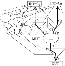
Figure 3. Test environment generation example. An unrolled view.
Consider as an example, a simplification of the ADD for the Greatest Common Division (GCD) benchmark presented in Figure 3. Without loss of generality in this ADD the control state information and the data registers have been removed and the circuit has been unrolled by applying time-frame expansion in order to improve the readability of the diagram. (Note, that the original GCD benchmark still contains a data dependent loop, which has been unrolled in Figure 3).
Assume that our task is generating a test environment for the subtraction module (MUT) in Figure 3. The output value of MUT will be propagated to the primary output OUT only if the first value input of the corresponding assignment decision is 1. Therefore we set the corresponding condition input of the ADN to C1. When we justify this particular condition input and the symbols at the MUT inputs according to the propagation rules presented in [10], then the strict interpretation of these rules would lead into a contradiction (See Figure 2a). However, the weak interpretation (also used in [11]) would still allow the following test environment: IN1=Cg and IN2=Cg. Note, that in current situation the weak rules are preferable since they at least allow testing part of the MUT while the strict rules would not generate any test environment at all.
III. CONSTRAINT-BASED UNTESTABILITY PROOF FLOW As opposed to the bottom-up test environment generation presented in Section 2, the constraint-driven deterministic untestability identification method proposed in current paper is based on the top-down approach. The method contains three main phases. During the first phase, the full set of constraints for setting up a test path to test an RTL module are extracted at the high-level. During the second phase this set of constraints is minimized. The third phase generates deterministic tests to the low-level module taking into account the path constraints.
Figure 4. Constraint-based untestability proof flow
Cq Cg
?
conflict in the strict interpretation
Cq Cg
Cg
resolves in the weak interpretation
Cq Cq
─
MUT :
OUT
= >
IN1=Cg IN2=Cg
O
O
! !
C1 C0
Cg C1 Cg C1
Cg Cg
Cq Cq
Figure 4 presents the corresponding test flow. We apply RTL ATPG Decider [16] in order to extract the constraints for accessing the MUT. Decider activates as many sets of constraints as there are test paths for that module in a bounded limit of clock-cycles. In [16], test constraints were utilized to propagate test patterns to and from the MUT. However, in this paper the purpose is to process the set of constraints in order to derive conditions for a dedicated logic-level ATPG in proving untestability. The constraints are minimized as shown in the next Section, translated into VHDL and synthesized to logic- level using Synopsys Design Compiler. Subsequently, the constraint-driven logic-level ATPG is run. As a result we obtain the list of sequentially untestable faults in the MUT as well as test patterns for the entire design.
IV. CONSTRAINT-BASED TEST ENVIRONMENT
In this Section we explain minimization of the test path constraints for a MUT. We show how to compute the constraint-based test environment from the set of test constraints. For the sake of completeness we briefly summarize the concept of test generation constraints below.
In order to extract the RTL constraints for a MUT, an RTL ATPG tool Decider [16] is applied. The high-level test generation constraints considered by Decider are divided into three categories. These are path activation constraints, transformation constraints and propagation constraints. Path activation constraints correspond to the logic conditions in the control flow graph that have to be satisfied in order to perform propagation and value justification through the circuit. Transformation constraints, in turn, reflect the value changes along the paths from the inputs of the high-level MUT to the primary inputs of the whole circuit. These constraints are needed in order to derive the local test patterns for the module under test. Propagation constraints show how the value propagated from the output of the MUT to a primary output is depending on the values of the signals in the system. The main idea here is to guarantee that fault effect will not be masked when propagated.
All the above categories of constraints are represented by common data structures and manipulated by common procedures for creation, update, modeling and simulation.
Note, that the extracted constraints consist of operations on primary inputs and constants. Furthermore, the exponential size complexity of the constraints is avoided by uniting multiple occurrences of the same variable (i.e. the literals) in the constraints at each time step into one single fanout variable. The size requirements for the constraints are linear with respect to justification time-frames and they represent a subset of the expanded time-frame model of the circuit.
Consider Figure 5, which gives the ADD of the full set of constraints for the MUT from the example of Figure 3. In other words, the MUT can only be tested using one of the two test paths presented in Figure 5a and 5b. The two paths are identical except for the fact that the primary inputs IN1, IN2 are swapped in them.
a) b)
Figure 5. Full set of test path constraints for MUT
Note, that from the point of view of accessing the MUT these two environments are equivalent. It is irrelevant which primary input is used in applying the test patterns when representing the constraint-based test environment for proving untestability. Therefore, we denote the value justified from the i-th input of the MUT by xk and the value propagated from the MUT output by y.
The constraints C1 and C2 both consist of two sub- constraints C1,1, C1,2 and C2,1, C2,2, respectively. C1,1 (which is equivalent to C2,1) states that x1 must not be equal to x2. C1,2
(equivalent to C2,2) states that x1 must be greater than x2. Since all the sub-constraints within a constraint should hold simultaneously they be combined using the conjunction operator. In turn, all the constraints are combined using the disjunction operation because any one of the test paths may be used for accessing the MUT. In general case for constraints Ci each consisting of sub-constraints Ci,j the constraint- environment for proving sequential untestability is calculated using the following formula:
(1)
Subsequent to combining the test path constraints constraint minimization is performed. For the example in Figure 5 we obtain:
. )
( ) ( ) ( )
(x1≠x2 ∧ x1>x2 ∨ x1≠x2 ∧ x1>x2 =x1>x2 Figure 6 shows the ADD for the minimized constraint- based environment resulting for testing the MUT of the example presented in Figure 3. The constraint shows that the MUT (a subtractor) may only be accessed when the first input of it, i.e. x1 is greater than the second one, x2.
Figure 6. Constraint-based test environment for MUT
−
MUTy
>
x1 x2
Constraint
, j
.
i j i
∧ C
∨
−
MUT:
OUT
>
IN2 IN1
=
!
&
x1 x 2
y C2:
−
MUT:
OUT
>
IN1 IN2
=
!
&
x1 x2
y C1:
C1,1: C1,2: C2,1: C2,2:
V. DISCUSSION ON THE EFFECT OF THE TOP-DOWN PROOF Existing high-level ATPG methods do not allow proof of sequentially untestable stuck-at faults. An exception is a previous work by the authors where a specific class of untestable register control faults were proven untestable by applying model-checking at the RTL [6]. The current work considers the general case of sequentially untestable stuck-at faults within RTL modules.
As a side-effect of our study, we show that the top-down test environment generation is more accurate than the bottom- up one. In particular, the strict interpretation of Ghosh’s algebra leads to overly pessimistic results because tests for some MUTs are aborted due to justification conflicts. On the other hand, the weak interpretation is too optimistic and can also lead to loss of fault coverage because some of the test patterns that are expected to cover faults in the MUT do not propagate.
Consider the case where in a bottom-up scenario we have a deterministic test Tq generated for the MUT reaching the maximum fault coverage Wq for the module. Then, we generate the test environment for the module and substitute Tq into the test environment. Due to the test path constraints the actual fault coverage that can be achieved for the MUT inside the network is Wa, which is generally lower than the fault coverage Wq. However, when we fault simulate Tq substituted into the test environment we obtain a fault coverage Wr, where Wr ≤ Wa≤ Wq.
In other words, the bottom-up approach may lose some fault coverage with respect to the top-down one because the set of the tests to choose from is restricted to Tq. If the local test generation algorithm for the MUT had had knowledge about the test path constraints it would have generated a different test Ta, whose fault coverage would have been equal to Wa. Furthermore, the remaining faults inside the MUT would have been proven untestable. Thus, a deterministic ATPG taking into account the test path constraints is necessary in order to achieve maximum fault coverage and also to prove untestability within sequential circuits. Experiments with the constraint-driven deterministic ATPG presented in Section 6 show that the difference between the coverages Wr and Wa may be even as high as 8-14 per cent of stuck-at coverage.
VI. EXPERIMENTAL RESULTS
In order to evaluate the hierarchical untestability identification and test generation method, experiments on HLSynth92 and HLSynth95 benchmarks were run. In addition, to compare the solution with the traditional bottom-up approach (e.g. [10]) and assess its fault efficiency, a detailed case-study was carried out.
Table 1 presents the characteristics of the example circuits used in test pattern generation experiments in this paper. The following benchmarks were included to the test experiment: a Greatest Common Divisor (GCD), an 8-bit sequential multiplier (MULT8x8), and a Differential Equation (DIFFEQ). In the Table, the number of single stuck-at faults, the number of primary input and primary output bits, and the number of
registers, multiplexers and functional units in the RTL code are reported, respectively. The final column presents the limit for control part FSM cycles (i.e. the maximum times the same control state is traversed) as the bound for the untestability proof. This bound is dependent on the design functionality and can be set by the test engineer.
TABLE I. BENCHMARK CHARACTERISTICS
In Table 2, comparison of test generation results of three ATPG tools on the hierarchical benchmark designs are presented. This comparison was carried out in order to show the time needed for extracting the constraint-based environment as explained in Section 4. The tools include a logic-level deterministic ATPG Hitec [18], a genetic algorithm based Gatest [19], hierarchical ATPG Decider applied in current paper. Columns ‘F.C., %’ give the single stuck-at fault coverages of the test patterns generated. Columns ‘time, s’ stand for test generation run-times in seconds. As it can be seen the three sequential designs analyzed introduce a serious challenge to the deterministic and genetic algorithm-based ATPG tools. For the former, the search space becomes too large and many faults have to be dropped after a time-out value has been encountered. For the latter, the genetically engineered vectors are unable to create tests for faults that require specific sequences for activation and propagation.
TABLE II. COMPARISON OF SEQUENTIAL ATPG circuit HITEC GATEST Decider F.C., % time, s F.C., % time, s F.C., % time, s gcd 59.11 365 86.13 190.7 90.95 677.4 mult8x8 65.9 1243 69.2 821.6 74.7 93.7 diffeq 96.2 13,320 96.40 3000 97.09 453.7
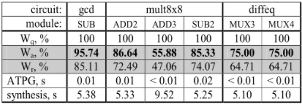
Table 3 shows experiments of the constraint-driven ATPG developed in this paper. The experiments present comparison of the proposed method to the bottom-up paradigm [10]. For creating the test library for the bottom-up approach, the modules were first tested by the ATPG in a stand-alone mode. As a result a test sequence Tq yielding 100 % stuck-at fault coverage Wq was obtained. The proposed top-down constraint- driven ATPG reached fault coverage Wa which was less than Wq because of the constraints when accessing the module under test that was embedded into the network. However, the fault efficiency of the proposed approach was always 100 % for all the modules.
When test Tq was substituted to the test environment in a bottom-up manner then fault coverage Wr was reached, which was always lower than Wa because some of the tests were invalidated by sequential dependencies. In fact, Wr was considerably lower (by 8-14 %) for all the four modules analyzed. Thus, the proposed top-down method was capable of
circuit # faults PI bits PO bits # reg. # mux # FU gcd
mult8x8 diffeq
472 2356 10326
33 17 81
16 16 48
3 7 7
4 4 9
3 9 5
limit 5 8 7
reaching maximum fault coverage for the analyzed module and proving all of the sequentially untestable faults in them.
The test environment synthesis from VHDL to logic-level using Synopsys Design Compiler remained almost constant and was around 5 to 10 s per module while the deterministic constraint-based ATPG spent less than 0.02 s per module under test. The synthesis and test experiments were carried out on a Sun-Fire-V250 station with 1.28 GHz sparcv9 processor under Solaris 2.9 OS.
TABLE III. CONSTRAINT-DRIVEN TOP-DOWN ATPG VERSUS BOTTOM-UP
ATPG RESULTS FOR CIRCUIT MODULES
circuit: gcd mult8x8 diffeq module: SUB ADD2 ADD3 SUB2 MUX3 MUX4 Wq, % 100 100 100 100 100 100 Wa, % 95.74 86.64 55.88 85.33 75.00 75.00 Wr, % 85.11 72.49 47.06 74.07 64.71 64.71 ATPG, s 0.01 0.01 < 0.01 0.02 < 0.01 < 0.01 synthesis, s 5.38 5.33 9.52 5.25 5.10 5.10
Table 4 presents detailed statistics of the circuits analyzed. The Table lists the total number of stuck-at faults in the whole circuit, the number of tested faults, number of unobservable/uncontrollable faults, the number of faults proven sequentially untestable by the proposed constraint- based approach and finally the number of all the remaining faults. The experiments show the efficiency of the constraint- driven engine in untestability identification. Though the method quickly classifies untestable faults caused by sequential untestability in the considered modules with 100 % fault efficiency, there remains a number of faults which are still neither tested nor proven untestable. Some of these remaining faults can be tested or proven untestable by traditional approaches at the logic-level.
TABLE IV. DISTRIBUTION OF FAULTS
gcd mult8x8 diffeq
# total faults 472 2356 10326
# tested faults 439 1737 9867
# unobs./uncontr. 28 195 252
# seq. untestable flts 4 156 68
# remaining faults 1 268 139
VII. CONCLUSIONS
The paper introduces a new method and tool for hierarchical untestable stuck-at fault analysis of non-scan sequential circuits. The method is based on extracting and minimizing RTL test path activation constraints that drive a dedicated logic-level deterministic ATPG. Experiments show that the tool is capable of generating tests yielding maximum fault efficiency for the embedded modules under test. To the best of the authors’ knowledge this is the first method that can prove sequential untestability starting from the RTL.
In addition, our study shows that traditional test generation at RTL based on symbolic test environment generation is too optimistic due to the fact that constraints in accessing the modules under test have been ignored. Experiments presented
in this paper showed that bottom-up strategies caused a decrease of stuck-at fault coverage up to the range of 8-14 % in the modules tested when compared to the proposed approach. This short-coming is now overcome by the proposed constraint-based method which obtains 100 per cent stuck-at fault efficiency for all the modules considered.
ACKNOWLEDGMENTS
The work has been supported by European Commission FP 7 project DIAMOND, by Research Centre CEBE funded by European Union through the European Structural Funds and by Estonian Science Foundation grants 7068 and 7483.
REFERENCES
[1] V. D. Agrawal and S. T. Chakradhar, “Combinational ATPG theorems for identifying untestable faults in sequential circuits,” IEEE Trans Comput.-Aided Des., vol. 14, no. 9, pp. 1155–1160, Sep. 1995.
[2] M. A. Iyer, D. E. Long, and M. Abramovici, “Identifying sequential redundancies without search,” in Proc. 33rd Annu. Conf. DAC, LasVegas, NV, Jun. 1996, pp. 457–462.
[3] Q. Peng, M. Abramovici, and J. Savir, “MUST:Multiple stem analysis for identifying sequential untestable faults,” in Proc. Int. Test Conf., Atlantic City, NJ, Oct. 2000, pp. 839–846.
[4] D. E. Long, M. A. Iyer, M. Abramovici, “FILL and FUNI: Algorithms to identify illegal states and sequentially untestable faults,” ACM Trans. Des. Automat. Electron. Syst., vol. 5, no. 3, pp. 631–657, Jul. 2000. [5] H.-C. Liang, C. L. Lee, and E. J. Chen, “Identifying untestable faults in
sequential circuits,” IEEE Des. Test. Comput., vol. 12, no. 3, pp. 14–23, Sep. 1995.
[6] J. Raik, H. Fujiwara, R. Ubar, A. Krivenko. “Untestable fault identification in sequential circuits using model-checking”. ATS, pp. 667- 672, 2008.
[7] B. T. Murray, J. P. Hayes, "Hierarchical test generation using precomputed tests for modules", Proc. ITC, pp.221-229, 1988.
[8] I. Ghosh, M. Fujita, “Automatic test pattern generation for functional RTL circuits using assignment decision diagrams”, Proc. DAC, pp. 43- 48, 2000.
[9] V. Chayakul, D. D. Gajski, L. Ramachandran, “High-Level Transformations for Minimizing Syntactic Variances”, DAC, pp. 413- 418, 1993.
[10] L. Zhang, I. Ghosh, M. Hsiao, “Efficient Sequential ATPG for Functional RTL Circuits”, Int. Test Conf., pp.290-298, 2003.
[11] H. Fujiwara, C. Y. Ooi, Y Shimizu, “Enhancement of Test Environment Generation for Assignment Decision Diagrams”, 9th IEEE Workshop on RTL and High Level Testing, Nov. 27-28, 2008.
[12] J. Lee, J.H. Patel, "Architectural level test generation for microprocessors", IEEE Trans. CAD, pp. 1288-1300, Oct. 1994.
[13] J. Raik, R. Ubar. Sequential Circuit Test Generation Using Decision Diagram Models, Proc. of the DATE Conference, pp. 736-740, 1999. [14] V. Vedula, J. Abraham, "FACTOR: A Hierarchical Methodology for
Functional Test Generation and Testability Analysis," DATE Conf., 2002.
[15] G. Jervan et al., "High-Level and Hierarchical Test Sequence Generation", IEEE HLDVT, Cannes, 2002.
[16] T. Viilukas, J. Raik, M. Jenihhin, R. Ubar, A. Krivenko, "Constraint- based test pattern generation at the register-transfer level", 13th IEEE DDECS Symposium, 2010, pp. 352-357.
[17] The ECLiPSe Constraint Programming System http://eclipse-clp.org/ [18] T. M. Niermann, J. H. Patel, "HITEC: A test generation package for
sequential circuits", Proc. EDAC, pp. 214-218, 1991.
[19] E. M. Rudnick, et al. "Sequential circuit test generation in a genetic algorithm framework", Proc. DAC, pp. 698-704, 1994.
![Figure 4 presents the corresponding test flow. We apply RTL ATPG Decider [16] in order to extract the constraints for accessing the MUT](https://thumb-ap.123doks.com/thumbv2/123deta/5753632.27174/4.892.467.801.103.327/figure-presents-corresponding-apply-decider-extract-constraints-accessing.webp)