This user manual is copyright of AIM srl. All procedures here illustrated can change also substantially; it is thereby suggested to always refer to our website www.aim- sportline.com to know the updated procedures.
AIM reserves the right to periodically update and re-issue the documentation without any obligation to notify anyone about such changes.
AIM cannot be held responsible for any mistake contained in this user manual or for damages resulting by the supply, working or usage of all parts (hardware, software and documentation).
Microsoft Windows XP and Microsoft Vista are registered trade marks of Microsoft Corporation.
INDEX
INDEX ... 2
Chapter 1 – Race Studio 2 software ... 6
1.1 – Compatibility between Race Studio 2 and operative systems ... 6
Chapter 2 – Installing Race Studio 2 and the USB Driver ... 7
2.1 – Preliminary operation. ... 7
2.2 – Installing Race Studio 2 under Microsoft Windows XP ... 8
2.3 – Troubleshooting ... 12
2.4 – Installing Race Studio 2 under Microsoft Windows Vista ... 13
2.5 – Installing the USB driver with “Run as Administrator” procedure ... 15
2.6 – Troubleshooting ... 18
2.7 – Race Studio 2 visualization problems ... 19
Chapter 3 – System identification ... 22
3.1 – System identification of MyChron3 ... 23
3.2 – System identification of other loggers. ... 24
Chapter 4 – How to configure MyChron3 kart Plus/Gold/Extreme ... 25
4.1 – Creating a new configuration ... 28
4.2 – Channels ... 29
4.3 – System configuration ... 30
4.3.1 – Display language box ... 30
4.3.2 – Speed box ... 30
4.3.3 – Shift Lights box ... 31
4.3.4 – RPM box ... 31
4.3.5 – Channels alarm boxes ... 31
4.3.6 – Lap box ... 32
4.3.7 – Gear sensor box ... 32
4.3.8 – Unit of measure box ... 32
4.4 – Transmitting the configuration ... 33
4.5 – Auto calibration of the accelerometer (Gold/Extreme only) ... 33
4.6 – Gear Calculation ... 33
4.7 – Online ... 33
Chapter 5 – How to configure MyChron3 Car/Bike Plus/Gold/Extreme ... 34
5.1 – Creating a new configuration ... 37
5.1.1 – MyChron3 Plus/Gold Bike Plug&Play configurations ... 38
5.1.2 – MyChron3 Gold Snow Mobile configuration ... 39
5.2 – Channels ... 40
5.3 – Creating a custom sensor ... 41
5.4 – System configuration ... 41
5.4.1 – System configuration of MyChron3 Gold Snow Mobile ... 42
5.5 – Transmitting the configuration ... 43
5.6 – Sensors calibration and auto-calibration ... 43
5.7 – Gear calculation ... 43
5.8 – Online ... 43
Chapter 6 – How to configure MyChron3 Log/Visor/XGLog ... 44
6.1 – Premise on MyChron3 Log/Visor/XGLog ... 47
6.2 – Creating a new configuration ... 47
6.2.1 – MyChron3 XG Log FR2000J configuration ... 48
6.3 – Channels ... 49
6.3.1 – MyChron3 Visor and MyChron3 XG Log FR2000J channels ... 50
6.4 – Creating a custom sensor ... 50
6.5 – System configuration ... 50
6.5.1 – Speed box ... 51
6.5.2 – Shift Light box ... 51
6.5.6 – Gear sensor box ... 53
6.6.7 – Measure unit box ... 53
6.5.8 – System configuration of MyChron3 XG Log FR2000J ... 53
6.6 – Transmitting the configuration ... 54
6.7 – Sensors calibration and auto-calibration ... 54
6.8 – Gear calculation ... 54
6.9 – Online ... 54
Chapter 7 – How to configure MXL Strada/Pista/Pro/Pro05 ... 55
7.1 – System manager window ... 57
7.1.1 – Select configuration layer ... 60
7.2 – Creating a new configuration ... 61
7.2.1 – MXL Strada/Pista and Pro05 Plug&Play configurations ... 62
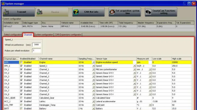
7.3 – Channels ... 63
7.3.1 – Speed panels ... 63
7.3.2 – Channels table ... 64
7.4 – Creating a custom sensor ... 67
7.5 – System configuration ... 67
7.5.1 – RPM box ... 67
7.5.2 – Gear sensor box ... 68
7.5.3 – Shift light box ... 68
7.5.4 – Channel for alarm and measure boxes ... 69
7.5.5 – Speed box ... 70
7.5.6 – Lap box ... 71
7.5.7 – Use GPS Lap timer box ... 71
7.5.8 – Condition enabling checked alarms box ... 72
7.5.9 – Enable static string and welcome message boxes ... 75
7.6 – Configuring the CAN expansions ... 76
7.7 – Transmitting the configuration ... 76
7.8 – Sensors calibration and auto-calibration ... 76
7.9 – Gear calculation ... 76
7.10 – Online ... 76
Chapter 8 – How to configure DaVid ... 77
8.1 – System manager window ... 79
8.1.1 – Select configuration layer ... 80
8.2 – Creating a new configuration ... 82
8.3 – Channels ... 83
8.3.1 – RPM panel ... 84
8.3.2 – Speed panel ... 84
8.3.3 – Gear sensor panel ... 85
8.3.4 – Reference speed panel ... 85
8.3.5 – Channel table: ... 86
8.4 – Creating a custom sensor ... 88
8.5 – How to configure DaVid displays ... 88
8.6 – How to configure DaVid ... 88
8.6.1 – Video Configuration Manager box: ... 91
8.6.2 – Video objects limits ... 93
8.6.3 – Visualization box: ... 94
8.6.4 – TV Standard box: ... 95
8.6.5 – Possible graphical visualization problems. ... 95
8.6.6 – Sampling frequency ... 96
8.7 – Transmitting the configuration ... 96
8.8 – Sensors calibration and auto-calibration ... 96
8.9 – Gear calculation ... 96
8.10 – Online ... 96
Chapter 9 – How to configure EVO3 Pro/Pista ... 97
9.1 – System manager window ... 99
9.1.1 – Select configuration layer ... 102
9.3 – Channels ... 104
9.3.1 – Speed panels ... 106
9.3.2 – Channel Table ... 107
9.4 – Creating a custom sensor ... 110
9.5 – System configuration ... 110
9.5.1 – RPM box ... 110
9.5.2 – Lap box ... 111
9.5.3 – Use GPS lap timer box ... 111
9.5.4 – Gear sensor box ... 112
9.5.5 – Speed reference box ... 112
9.5.6 – Output signal on pin 5 of RPM connector box ... 113
9.6 – How to configure EVO3 Pro/Pista displays ... 114
9.7 – Configuring CAN expansions ... 114
9.8 – Transmitting the configuration ... 114
9.9 – Sensors calibration and auto-calibration ... 114
9.10 – Gear calculation ... 114
9.11 – Online ... 114
Chapter 10 – How to configure EVO4 ... 115
10.1 – System manager window ... 117
10.1.1 – Select configuration layer ... 120
10.2 – Creating a new configuration ... 121
10.3 – Channels ... 122
10.3.1 – Speed panels ... 122
10.3.2 – Channel Table ... 123
10.4 – Creating a custom sensor ... 125
10.5 – System configuration ... 125
10.5.1 – RPM box ... 125
10.5.2 – Gear sensor box ... 126
10.5.3 – Lap box ... 126
10.5.4 – Use GPS Lap timer box ... 127
10.5.5 –Reference speed box ... 127
10.5.6 – Output signal on pin 5 of RPM connector ... 128
10.6 – How to configure EVO4 displays ... 130
10.7 – Configuring CAN expansions ... 130
10.8 – Transmitting the configuration ... 130
10.9 – Sensors calibration and auto-calibration ... 130
10.10 – Gear calculation ... 130
10.11 – Online ... 130
Chapter 11 – How to configure ECU Bridge ... 131
11.1 – System Manager window ... 133
11.1.1 – Select configuration layer ... 135
11.2 – Creating a new configuration ... 136
11.3 – Channels ... 137
11.4 – System configuration ... 138
11.4.1 – RPM box ... 138
11.4.2 – Gear sensor box ... 138
11.4.3 – Lap box ... 139
11.4.4 – Use GPS Lap timer box ... 139
11.4.5 –Reference speed box ... 140
11.5 – How to configure ECU Bridge displays ... 140
11.6 – Transmitting the configuration ... 140
11.7 – Gear calculation ... 140
11.8 – Online ... 140
Chapter 12 – How to create a custom sensor ... 141
Chapter 13 – How to transmit the configuration ... 144
14.2 – Sensors auto calibration procedure ... 147
14.3 – Gear sensor calibration procedure ... 147
Chapter 15 – Gear calculation procedure ... 150
Chapter 16 – How to configure CAN expansions ... 153
Chapter 17 – How to configure AIM displays ... 157
17.1 – How to configure MyChron3 Dash ... 157
17.1.1 – How to configure MyChron3 Dash for DaVid ... 157
17.1.2 – How to configure MyChron3 Dash for EVO3 Pro/Pista ... 159
17.2 – How to configure TG Dash ... 160
17.2.1 – TG Dash for DaVid ... 160
17.2.2 – TG Dash for EVO3 Pro/Pista and EVO4 ... 161
17.3 – How to configure Formula Steering Wheel ... 161
Chapter 18 – Online ... 163
Chapter 19 – How to download data ... 165
19.1 – Download data from MyChron3 (all versions) and DaVid ... 166
19.2 – Downloading data from other systems ... 171
0
Chapter 1 – Race Studio 2 software
Race Studio 2 is the application properly designed and developed by AIM to configure its loggers and analyze their data using a PC. It is made up of two software: Race studio Configuration and Race Studio Analysis.
This user manual refers to the Race Studio Configuration (from 2.30.05) only.
Race Studio 2 developed following the evolution of AIM loggers and ever improving its potentialities. Thanks to the configuration, the user can better customize its logger to take the most out of it.
With Race Studio 2 it is possible to integrate in a flexible and dynamic system all the external expansion modules and the innovative devices that AIM Research and Development Dept. creates as well as all the custom sensors that any user can connect to his logger.
Configuring a logger with Race Studio 2 means adapting it to one’s needs, taking the most out of it.
1 9
1.1 – Compatibility between Race Studio 2 and operative systems
Race Studio 2 has been developed to guarantee the maximum working reliability and its correct working has been tested with the following operative systems: Microsoft Windows XP and Microsoft Windows Vista 32 bit.All operative systems (Linux, Unix, Macintosh®) not indicated in this tutorial are to be considered not supported by this application.
Note: at present it is not possible to install AIM USB driver under Microsoft Window Vista 64 bit.
For any problem it is suggested to check www.aim-sportline.com website to verify if any recent news has been issued and, if not, to contact the technical support at www.aim-sportline.com/pages/tech_support/section_tech_support.php.
1
Chapter 2 – Installing Race Studio 2 and the USB Driver
To configure most of AIM loggers it is necessary to install Race Studio 2 and the AIM USB driver.
2 0
2.1 – Preliminary operation.
Before starting software installation disconnect any AIM logger from the PC USB port and close all running applications.
A suggested preliminary operation is to check WindowsTM “Driver signing” setting.
• Follow this path: Start ¨ setting ¨ Control Panel ¨ System and select
“Hardware” layer (figure below on the left).
• Click on “Driver signing” and select “Warn – Prompt me each time to choose an action” (figure below in the right).
• Confirm pressing OK button and close all windows.
6 6
2.2 – Installing Race Studio 2 under Microsoft Windows XP
Before installing the software close all applications and insert Race Studio 2 CD. If
“auto play” option is enabled the installation starts automatically, otherwise click twice on “SETUP” icon.
In case of very first Race Studio 2 installation the window on the right appears. It allows to select the window where to install the software.
Press “Browse” button to select Race Studio 2 installation folder.
Press “Next” to install the software in the default folder X/program files/AIM, where
“X” is the hard disk where the operative system is installed.
In case of new release of Race Studio 2 the window on the right appears: enable
“New Release of Race Studio 2” checkbox and click on “Next>”
From here onward the installation is the same. The window on the right appears and Race Studio 2 is installed.
When the installation is over, in case of new release of Race Studio 2, the window on the right appears. Click on “Finish”. Installation is completed.
In case of very first installation, on the contrary, the software starts AIM USB driver installation and the window on the right appears.
Disconnect any AIM USB cable from the PC USB port and click on “Start” button.
Close all applications and click on “Start”.
Click on “Continue Anyway”.
Click on “Continue”.
Three panels will assist in the following steps.
Connect the USB cable to the PC USB port and switch the logger on. Wait some seconds and the following panel appears.
This pop up informs the user that the logger is correctly connected to the PC. Note: when the procedure is over, connecting the logger to another PC USB port, the system could ask for USB driver installation on the new port too.
Enable “No, not now” checkbox and click on “Next>”.
Enable “Install the software automatically (recommended)” checkbox and click on
“Next >”.
Click on “Finish”.
Click on “OK”.
Click on “Finish”.
After the first installation two new icons, shown on the right, appear on the PC desktop: Race Studio 2 (Configuration) icon and Race Studio Analysis one. For this last one refer to the proper user manual.
Race Studio Configuration icon
Race Studio Analysis icon
When the first Race Studio 2 installation is over, all new release installations will jump driver installation (please remember to periodically check www.aim- sportline.com download/software area).
6 7
2.3 – Troubleshooting
In case driver installation ends incorrectly for any reason, starts maintenance procedure running AIM_USB_Inst_2008.exe. Follow this path: C:\Program files \ AIM
\ AIM_USB_DRIVER_2008.
Run AIM_USB_Inst_2008.exe file.
6 8
2.4 – Installing Race Studio 2 under Microsoft Windows Vista
Microsoft Vista™ operative system introduced more rigid safety procedures.Note: AIM has not yet obtained Microsoft “signature”. This procedure is ongoing and, once finished, will make the installation completely automatic.
Installing “unsigned” driver needs to run the program “As administrator” that means starting Microsoft Vista™ using an “administrator” account. PC are normally sold with this account.
Race Studio 2 installation creates a new icon on the PC desktop, that allows the user to start USB driver installation as “Administrator”.
Before starting the installation, ensure that the logger is NOT connected to the PC USB port. In case it is, disconnect it.
Insert Race Studio 2 CD in the CD Rom: if “auto play” option is enabled the installation starts automatically, otherwise click twice on “SETUP” icon.
In case of Race Studio 2 very first installation the window on the right appears. It allows the user to select the software installation folder.
Click on “Browse” to select Race Studio 2 destination folder or on
“Next” to install the software in X/program files/AIM folder, where
“X” is the hard disk where the operative system is installed on.
In case of new release of Race Studio 2, the window on the right appears: enable the checkbox “New Release of Race Studio 2” and click on “Next>”.
The window on the right appears.
After the installation – in case of new release of Race Studio 2 – the window on the right appears.
Click on Finish. The installation procedure is completed.
In case of very first installation the window on the right appears.
Click on “OK” button, to continue the installation.
Click on the question mark to know the <Run as Administrator> procedure. The following window appears.
It shows how to execute <Run as Administrator> procedure; click on
“OK” to continue.
Click on “Finish”.
2 1
2.5 – Installing the USB driver with “Run as Administrator”
procedure
As explained in the image on the right, right click on AIM_USB_2008 icon on the PC desktop and select “Run as Administrator” option.
Click “YES” to continue.
Disconnect any USB cable and click on “START”.
Click on “START”. AIM USB driver installation starts.
Click on “OK”.
Click on “Install this driver software anyway”.
Click on “Continue”.
Connect the USB cable to the PC USB port.
During Race Studio 2 and AIM USB driver installation, three new icons appear on the desktop PC:
AIM USB Driver icon Race Studio 2 (Configuration)
icon Race Studio Analysis icon
As far as Race Studio Analysis icon is concerned, refer to the proper user manual.
6 9
2.6 – Troubleshooting
In case USB driver installation ended incorrectly for any reason it is possible to start the maintenance procedure repeating the “Run as Administrator” procedure.
As shown in the figure on the right, right click on AIM_USB_2008 icon on the PC desktop and select “Run as administrator” option.
The panel on the right appears: click on
“Reinstall driver”.
The first step completely erases the first installation.
The system asks for confirmation.
Click on “Yes” to complete the new installation.
Click on “No” to quit and restart installation procedure later.
7 0
2.7 – Race Studio 2 visualization problems
Running Race Studio 2 the display may show a misrepresented image like the one here below.
In this case it is necessary to change monitor settings.
Warning: close all running applications, Race Studio 2 included. This operation requires PC rebooting.
Here below the explanation of the procedure to modify monitor settings:
Follow this path:
“Start/Setting/ Control Panel /Display”. The window “Display Properties”, shown here on the right, appears.
Select “Settings” layer. Press “Advanced”.
Enable “Ask me before applying the new display settings” option.
Set DPI setting on “Normal (96 DPI)”
The window here below appears.
Press “OK”.
Press “Apply”.
The window here below appears:
Press “Yes”.
Press “OK”.
Press “Yes”.
The system reboots.
After rebooting run “Race Studio 2” and all works correctly.
2
Chapter 3 – System identification
All AIM systems are univocally identified by Race Studio 2 software. This allows to preliminarily check the communication between PC, software and the logger as to understand if the logger is supported by the software.
It is suggested to make a logger identification before starting any configuration. The procedure is:
• run Race Studio 2
• connect the USB cable to the PC and to the logger USB port
• switch the logger on
• press the button system identification. It is on Race Studio 2 menu bar, in the left vertical keyboard and in system manager window (the button is labelled “System Identification” for all MyChron3 loggers and “CAN-net Info” for the other systems).
If all works correctly, “System identification/CAN-NET info” window, shown below, appears.
MyChron3 logger identification window CAN-net info window (other systems)
7 1
3.1 – System identification of MyChron3
The window shows:
• Logger channels: number of channels of the logger
• Memory: memory size of the logger (no matter how much of it has already been used)
• Logger unique ID: logger serial number
• Date ID: logger production date
• Driver vers. and VID: information concerning the USB driver
• Booter (date and vers.): logger booter date and version
• Firmware (date and vers.): logger firmware date and version. It is suggested to check on www.aim-sportline.com that the logger firmware version is the latest available; if not, pls. download the latest one, install it and follow instructions that appear on the PC monitor.
7 2
3.2 – System identification of other loggers.
The window shows:
• N: index of the item in the list. This window recognizes all loggers in their order starting always from the Master one (in the figure above an MXL Pista);
• Category of logger: role of the logger in the CAN net (master or CAN expansion)
• Type of logger: type of device connected
• Expansion Name: role of the logger in the CAN network
• Logger ID: logger univocal serial number
• ID Date: logger production date
• Firmware Version: firmware version installed on the logger. It is suggested to check on www.aim-sportline.com website that the firmware version is the latest available; if not, pls. download the latest one, install it and follow the instructions that appear on the PC monitor.
• Firmware Date: firmware date.
3
Chapter 4 – How to configure MyChron3 kart
Plus/Gold/Extreme
To correctly configure, MyChron3 Kart (Plus/Gold/Extreme) use a PC and Race Studio 2 software.
MyChron3 Kart can be configured both via keyboard and via software but some parameters can be set only via software. To measure lateral acceleration (to create track maps), for instance, it is necessary to calibrate the internal accelerometer via software.
Before starting the configuration install Race Studio 2 and the USB driver as explained in Chapter 2.
Run the software clicking on Race Studio 2 icon and the window below appears.
In the title bar - white on a blue background in the figure above – you can see the version of Race Studio 2 installed on the PC.
Immediately under there is the menu bar, that is shown in a more immediate way on the left thanks to the graphic buttons: Go to Analysis (this button runs Race Studio Analysis software), Download data, AIM system manager, AIM system Identification, Online, AIM system calibration, Custom sensors manager, Select language.
From this window it is possible to perform all operations necessary to manage all AIM systems.
To enter configuration menu click on “AIM system manager”. A panel showing all systems managed through Race Studio 2 appears: double click on MyChron3 Kart Plus/Gold/Extreme button or click on it and then press “9Go to” button.
Race Studio 2 “System manager” window appears.
This window has two keyboards.
• General: shows “System manager” window. In the central part, with grey background, all configurations currently included in the software database are listed. In case of first configuration, the system shows automatically new configuration window.
• Configuration: allows to set or modify an existing configuration.
• Channels: allows to set all logger channels.
• System Identification: allows to identify the logger connected to the PC.
• Transmit: transmits a configuration. Needs the logger to be switched on and connected to the PC.
• Receive: reads and saves the configuration of the logger connected to the PC.
• Online: allows to verify that the configuration is correct and has been correctly transmitted to the logger and that all works properly.
• Calibrate: allows to calibrate/auto-calibrate the sensors that need it.
• New: creates a new configuration
• Delete: deletes a configuration
• Clone: clones a configuration.
• Import: imports a configuration from a file.
• Export: exports a configuration to a file.
• Exit: quits “System manager” window.
To work on a configuration click on any cell of that configuration row and the entire row is selected (highlighted in yellow).
7 3
4.1 – Creating a new configuration
Pressing “New” button in system manager window, this window appears:
Some parameters need to be set:
• Data logger type: select the logger to be configured.
• Vehicle name: insert the vehicle name.
• Speeds unit of measure: choose between km/h and Mph;
• Temperatures unit of measure: choose between °C and °F; Press “OK” to save (“Cancel” to quit without saving).
The system comes back to system manager window.
The next step is channels setting. Press “Channels” button.
7 4
4.2 – Channels
Pressing Channels button the window here below appears.
It shows all loggers channels with the related characteristics:
• Channel identifier: shows the channel label.
• Enabled/Disabled: shows the channel status (enabled/disabled). It can be modified double clicking on the cell except for RPM and SPD that can be modified only through system configuration window.
• Channel name: allows to name the channel.
• Sampling Frequency: allows to set each channel sampling frequency. This last one influences the total available time – highlighted by a box in the figure above – that diminishes increasing the sampling frequency because the memory fills up faster.
• Sensor type: allows to select the sensor installed on that channel from the drop down menu that appears clicking on that cell. Channels CH_1 and CH_2 are temperature channels: the logger can distinguish automatically a thermocouple from a thermo resistor and no configuration is needed. Channels CH_3 and CH_4 can be temperature or pressure channels: it is thereby necessary to configure them. CH_5 is the gear sensor installed in the gearbox that allows MyChron3 to measure the engaged gear; MyChron3 Gold/Extreme has got an internal accelerometer to measure lateral g. It allows to create track maps.
• Measure unit: show the selected unit of measure for each channel. It is possible to change it double clicking on the cell.
• High/Low scale: shows the range of values shown by the graph that will be created in Race Studio Analysis after data download.
• Param.1/Param2: values of RPM and speed set in system configuration window.
When all parameters have been set, it is necessary to transmit the configuration to the logger.
7 5
4.3 – System configuration
MyChron3 Kart Plus/Gold/Extreme has got 14 fully configurable coloured led; the 2 on the left and on the right of the display represent the 4 max and min alarm of the analog channels (temperatures and pressures), while the other 10 led on top of the display are the Shift lights that inform the pilot to shift gear.
To set alarms, high/low threshold values and configuration parameters it is necessary to complete the window shown here above.
1 1 24.3.1 – Display language box
It allows to select the display language from the drop down menu.
1 1 34.3.2 – Speed box
• Wheel circumference: fill in the kart wheel circumference (in mm or in inches); this value is fundamental to correlate the wheel revolution speed to the kart one.
• Pulses per wheel revolution: fill in the number of magnets installed on the
1 5 44.3.3 – Shift Lights box
Sets the 5 RPM values, each one corresponding to two of the coloured led placed on top of MyChron3.
Led colours: the first two on the left and on the right are green, the central two are orange and the last four are red. To set the RPM threshold values fill in the cases. The led switches progressively on and when the engine reaches RPM value set in the fifth case all led start blinking, warning the pilot to shift gear. If a value is set on 0 the corresponding led is disabled.
1 1 44.3.4 – RPM box
• Multiply factor: it is possible to choose among different values: for a one cylinder two strokes kart the proper value is /1.
• Max value: set the RPM high scale.
1 1 54.3.5 – Channels alarm boxes
These boxes (2 for MyChron3 Plus/Gold, 4 for MyChron3 Extreme) allow to set the channels threshold values linking them to the four lateral led of the system.
For MyChron3 Plus and Gold it is possible to connect the min and max threshold values to different Led while for MyChron3 Extreme max and min threshold values have to be connected to the same led. Insert max and min value corresponding to the sensors installed on the kart.
1 5 54.3.6 – Lap box
• Obscuring time: is a time period during which the lap receiver installed on the kart, after having sampled a lap signal, is “blind” (it does not record signals). This function is useful for split times management on tracks with more magnetic strips/optical transmitters: set obscuring time on a minimum value to sample split times; not to record split times, set obscuring time on a value lower than best lap time and higher then the time elapsed between last split and start/finish line.
• Number of split times: is the number of splits the track is divided in and corresponds to the number of magnetic strips/optical transmitters installed there.
1 1 64.3.7 – Gear sensor box
• None: not to see the engaged gear number.
• Calculated: to calculate the engaged gear number (see the related chapter for further information). In this last case, “Highest gear number” case is enabled: fill in the kart number of gears.
1 1 74.3.8 – Unit of measure box
• Speed Unit: choose between km/h and mph
• Temperature unit: choose between °C and °F.
When all configuration parameters have been set, click on “OK” button to save
7 6
4.4 – Transmitting the configuration
The procedure to transmit the configuration to the logger is the same for all AIM loggers. Refer to the related chapter for further information.
7 7
4.5 – Auto calibration of the accelerometer (Gold/Extreme only)
The auto-calibration procedure is the same for all AIM loggers. Refer to the related chapter for further information.2 2
4.6 – Gear Calculation
Refer to the related chapter for further information.
2 3
4.7 – Online
Online function is very useful to check the logger proper working. Refer to the related chapter for further information.
4
Chapter 5 – How to configure MyChron3 Car/Bike
Plus/Gold/Extreme
To correctly configure MyChron3 Car/Bike Plus/Gold/Extreme use a PC and Race Studio 2 software.
MyChron3 Car/Bike can be configured both via keyboard and via software but some channels, like these with temperature or pressure sensors, accelerometer or gyroscope, cannot be set via keyboard.
Before starting the configuration install Race Studio 2 and the USB driver as explained in Chapter 2.
Run the software clicking on Race Studio 2 icon and the window below appears:
In the title bar – white on a blue background in the figure – you can see the version of Race Studio 2 installed on the PC.
Immediately under there is the menu bar, that is shown in a more immediate way on the left thanks to graphic buttons: Go to Analysis (this buttons runs the analysis software Race Studio Analysis), Data download, AIM system manager, AIM system identification, Online, AIM System Calibration, Custom sensors management, Select language.
Through this window it is possible to perform all operations necessary to manage all AIM systems.
To enter configuration menu click on “AIM System manager”. A panel showing all systems managed through Race Studio 2 appears: double click on MyChron3 Car/Bike Plus/Gold/Extreme button or select it and click on “9Go to” button.
Race Studio 2 System manager window appears.
This window has two keyboards.
• General: shows “System manager window”. In the central part, with grey background, all configurations currently included in the software database are listed. In case of first configuration the software shows directly “New configuration” window.
• Configuration: allows to set or modify a configuration.
• Channels: allows to set all loggers channels.
• System Identification: allows to identify the logger connected to the PC.
• Transmit: transmits a configuration to the logger. It needs the logger to be switched on and connected to the PC.
• Receive: reads and saves the configuration of the logger connected to the PC.
• Online: allows to check that the configuration is correct and has been correctly transmitted to the logger and that all works properly.
• Calibrate: allows to calibrate/auto-calibrate the sensors that need it.
• New: creates a new configuration.
• Delete: deletes a configuration.
• Clone: clones a configuration.
• Import: imports a configuration from a database or from a file.
• Export: exports a configuration in a file.
• Quit: quits “System Manager” window.
To work on a configuration click on any cell of that configuration row and the entire row is selected (highlighted in yellow).
7 8
5.1 – Creating a new configuration
Pressing “New” button in “System Manager” window, this window appears.
Some parameters need to be set:
• Data Logger type: select the logger to be configured.
• Vehicle Name: insert the vehicle name.
• Speeds unit of measure: choose between km/h and Mph.
• Temperatures unit of measure: choose between °C and °F.
• Pressures unit of measure: choose between Bar and PSI. Press “OK” to save (“Cancel” to quit without saving).
The system comes back to system manager window.
The next step is channels setting. Press “Channels”.
1 5 65.1.1 – MyChron3 Plus/Gold Bike Plug&Play configurations
MyChron3 Plus/Gold Plug&Play kits for Bike installations include, beside the logger, all what is needed for an easy installation on the bike (wiring, bracket, screws, washers, etc.). At present, the most important models/brands have got their kits available. Refer to AIM corporate website www.aim-sportline.com for further information.
If the bike is completely corresponding to the stock one sold by the manufacturer, selecting the related configuration is enough to transmit it to the logger. In case, on the contrary, additional sensors have been installed, they need to be configured following the procedures here described.
Warning: all parameters set in Plug&Play configurations have been tested to work correctly. Refer to each kit user manual for any information concerning the configuration and to modify it.
1 5 75.1.2 – MyChron3 Gold Snow Mobile configuration
AIM produces a particular version of MyChron3 Gold for Snowmobile installations. This particular MyChron3 application is supported by the configuration labelled
“MyChron3 – SM – Gold”. When the logger has been correctly installed and the eventual additional sensors connected (refer to the related documentation for further information), it is necessary to configure the logger. Select the logger between these available in “New configuration” window.
Pressing “OK” the system comes back to System manager window. The next step is channels setting; press “Channels”.
7 9
5.2 – Channels
Pressing Channels button this window appears.
It shows all channels set on the logger with the related characteristics:
• Channel Identifier: shows channel label.
• Enabled/Disabled: shows channel status (enabled/disabled). It is modifiable with a double click on the cell except for RPM, Speed and Gear that can be modified only through System configuration window.
• Channel name: allows to name the channel.
• Sampling Frequency: allows to set each channel sampling frequency. This last one influences the total available sampling time – highlighted by a box in the figure above – that diminishes increasing the sampling frequency because the memory fills up faster.
• Sensor type: allows to select the sensor installed on that channel from the drop down menu that appears clicking on that cell. Channels CH_1-CH_4 support temperature or pressure sensors (MyChron3 Plus), potentiometers and Lambda probe (MyChron3 Gold/Gold XG). User can set the desired sensor selecting it from the drop down menu. Channel CH_5 is gear channel. MyChron3 Gold Bike allows to install an external gyroscope on channel CH_7 to create the track map while MyChron3 Gold/Gold XG (Car) has a lateral internal accelerometer (labelled ACC_1) for the same purpose.
• Measure unit: allows to select the sensor unit of measure.
• High/Low scale: shows the range of values visualized by the graph that will be created by Race Studio Analysis after data download.
• Param.1/Param2: the values of RPM and speed parameters set in system configuration window.
When all parameters have been set it is necessary to transmit the configuration to
8 0
5.3 – Creating a custom sensor
The procedure to create a custom sensor is the same for all AIM loggers. Refer to the related chapter for further information.
2 4
5.4 – System configuration
MyChron3 Car/Bike Plus/Gold/Extreme has 14 fully configurable alarm led; the 2 on the left and on the right of the display are the 4 high/low alarm led of the analog channels (temperatures and pressures), while the other 10 on top of the display are the Shift lights that warn the pilot to shift gear.
To set alarms, high/low threshold values and configuration parameters it is necessary to fill in the above reported window.
First of all select the display language red circled in the figure above. Note: in case of a Plug&Play kit this window is already configured.
This window is to be completed like that of MyChron3 Kart (see paragraph 4.2.) except for Gear sensor box, shown here below. Available options are:
• “None”: not to see the engaged gear on the display.
• “Potentiometer”: a gear potentiometer1 is available.
• “Calculated”: to calculate the engaged gear2; specify whether a neutral sensor is available or not if required.
1 See the related chapter for further information.
1 5 85.4.1 – System configuration of MyChron3 Gold Snow Mobile
In case of a MyChron3 Gold Snowmobile, configuration window is slightly different, as shown below. It has an additional box labelled “Shaft rotation speed”.
The window is to be completed like the other MyChron3 of this group (see paragraphs 4.2 and 5.2) except for Shaft rotation speed box, reported here below. Fill in the pulses for shaft revolution. This
value corresponds to the number of magnets installed on the snowmobile transmission shaft.
8 1
5.5 – Transmitting the configuration
The procedure to transmit the configuration to the logger is the same for all AIM loggers. Refer to the related chapter for further information.
2 5
5.6 – Sensors calibration and auto-calibration
When the configuration has been transmitted it is necessary to perform calibration procedure, to say auto-calibrate accelerometer, gyroscope and distance potentiometer and calibrate the gear sensor, the mid zero potentiometer and the zero based potentiometer installed on the vehicle.
See the related chapter for further information.
Warning: if potentiometers, gyroscope and accelerometers have not been correctly calibrated it is not possible to sample correct data, nor the engaged gear nor create the track map. It is recommended to pay particular attention to sensors calibration/auto-calibration procedures.
2 6
5.7 – Gear calculation
Refer to the related chapter for further information.
2 7
5.8 – Online
Online function is very useful to check the logger proper working. Refer to the related chapter for further information.
5
Chapter 6 – How to configure MyChron3 Log/Visor/XGLog
To correctly configure MyChron3 Log/Visor/XGLog, use a PC and Race Studio 2 software.
MyChron3 Log/Visor/XGLog can be configured both via keyboard and via software but some channels can only be set via software. Temperature or pressure sensors, as well as ECU signals cannot be set via keyboard, exactly like accelerometers, potentiometers, the gyroscope etc….
Before starting the configuration, install Race Studio 2 and the USB driver as explained in chapter 2.
Run the software clicking on the related icon and the window here below appears.
In the title bar – white on a blue background in the figure – you can see the Race Studio 2 version installed on the PC .
Immediately under there is menu bar, shown in a more intuitive way on the left thanks to the graphic buttons: Go to Analysis (this button runs Race Studio Analysis software), Data download, AIM system manager, AIM system identification, Online, AIM system calibration, Custom sensors management, Select language.
From this window it is possible to perform all operations necessary to manage all AIM systems.
To enter configuration menu click on “AIM system manager” button . A panel showing all systems managed through Race Studio 2 software appears: double click on
“M3Log/Visor XGLog” or select it and click on “9Go to” button.
Race Studio 2 “System manager” window appears.
Top and bottom keyboards allows the user to perform all needed operations to manage an AIM system. For further information concerning each button refer to the related paragraph in the chapter concerning MyChron3 Car/Bike Plus/Gold/Extreme configuration.
Central is the database of the available configurations. To work on one of them click on any cell of that configuration and the entire row is selected (highlighted in yellow).
8 2
6.1 – Premise on MyChron3 Log/Visor/XGLog
Systems managed through this button are: MyChron3 LOG Advanced, MyChron3 Visor, MyChron3 XG LOG FR2000J (configuration properly created for Japanese Formula Renault 2000 championship), MyChron3 XG LOG, MyChron3 LOG Bike and they differ from these previously explained because they can be connected to the engine control unit (from here onward ECU) of the vehicle.
For any information regarding the ECUs currently supported by AIM loggers, the procedures for a proper communication and connection between ECUs and AIM loggers, pls. refer to AIM corporate website at this link:
http://www.aim-sportline.com/pages/download/section_documentation_ecus.htm
2 8
6.2 – Creating a new configuration
Pressing “New” button in system manager window this window appears.
Some parameters need to be set:
• Data logger type: select the logger to be configured (please note: logger labelled M3 XG LOG FR2000J creates a configuration properly developed for Japanese Formula Renault 2000 championship);
• ECU Manufacturer: select the manufacturer of the ECU installed on the vehicle or none. This last option is only available for MyChron3 XG Log and MyChron3 Log Bike, the only loggers of this group that can work also without being connected to an ECU.
• ECU Model: select the ECU model or none.
• New configuration name: fill in the configuration name.
• Vehicle name: fill in the vehicle name.
• Speeds unit of measure: choose between km/h and Mph.
• Temperatures unit of measure: choose between °C and °F.
• Pressure unit of measure: choose between Bar and PSI. Press “OK” to save (“Cancel” to quit without saving).
The system comes back to system manager window.
The next step Is channels setting. Press “Channels”.
1 1 86.2.1 – MyChron3 XG Log FR2000J configuration
AIM produces a particular version of MyChron3 XG Log properly created for Japanese Formula Renault 2000 championship and labelled MyChron3 XG Log FR2000J. This particular application is supported by a configuration included in the available configurations database in MyChron3 Log/Visor XG Log menu. When the logger has been correctly installed and the sensors connected it is necessary to configure the logger. Select the logger between these available in “New Configuration” window.
Pressing “OK” the system comes back to System manager window. The next step is channels setting, press “Channels”.
8 3
6.3 – Channels
Pressing Channels button this window appears.
It shows all channels set on the logger with the related characteristics:
• Channel identifier: shows channel label. “ECU_X” are the ones received from the vehicle ECU.
• Enabled/Disabled: shows channel status (enabled/disabled). It can be modified with a double click on the cell except for RPM, speed and gear channel that are only modifiable through system configuration window.
• Channel name: allows to name the channel.
• Sampling frequency: allows to set each channel sampling frequency. This last one influences the total available sampling time, highlighted by a box in the figure above, that diminishes increasing the sampling frequency because the memory fills up faster.
• Sensor type: allows to select the sensor installed on that channel selecting it from the drop down menu that appears clicking on that cell. On channels from CH_1 to CH_4 (for MyChron3 XG Log FR2000J, MyChron3 Log Bike) or CH_5 (for MyChron3 Log Advanced, MyChron3 XG Log) it is possible to connect temperature or pressure sensors, potentiometers, Lambda probe and gyroscopes (except for MyChron3 Log Bike that has channel CH_7 devoted to the gyroscope). To set the desired sensor select it from the available sensors list. Channel CH_6 is the gear channel.
• Measure unit: allows to select the sensor unit of measure.
• High/Low scale: shows the range of values shown by the graph that will be created by Race Studio Analysis software after data download.
• Param.1: is the value of RPM or speed parameters set in system configuration window.
When all parameters have been set transmit the configuration to the logger.
1 5 96.3.1 – MyChron3 Visor and MyChron3 XG Log FR2000J channels
MyChron3 Visor, being just a dash, does not allow sensor installation on the different channels but only receives ECU signals.
MyChron3 XG Log FR2000J channels are already set but it is possible to set additional temperature and pressure sensors, potentiometers, gyroscope and Lambda probe on channels from CH_1 to CH_4.
2 9
6.4 – Creating a custom sensor
The procedure to create a custom sensor is the same for all AIM loggers. Refer to the related chapter for further information.
3 0
6.5 – System configuration
MyChron3 Log/Visor/XGLog has 14 fully configurable coloured led; the 2 on the left and on the right of the display are the four high/low alarm led of the analog channels (temperatures and pressures), while the other 10 led on top of the display are the Shift lights that warn the pilot to shift gear.
To set alarms, high/low threshold values and all configuration parameters it is necessary to complete the window shown here above.
First of all select the display language red circled in the figure above.
1 6 06.5.1 – Speed box
• Channel: select from the drop down menu the speed channel to be used as reference and that will be shown by the logger display, used for gear calculation (paragraph 5.7), for some Race Studio Analysis computations etc. Available options are: speed coming from the speed sensor, speed coming from the ECU and none.
• Wheel circumference: fill in the vehicle wheel circumference;
• Number of pulses per wheel revolution: fill in the number of pulses per wheel revolution (that corresponds to the number of magnets installed on the wheel).
1 1 96.5.2 – Shift Light box
Sets 10 led placed on top of MyChron3. Led colors: the first two on the left and on the right are green, the central two are orange and the last four are red. To set RPM threshold value fill in the cases. Led switches progressively on and when the engine reaches the RPM value set for Led 5 all led start blinking warning the pilot to shift gear. If a value is set on 0 the corresponding led is disabled.
1 2 06.5.3 – RPM box
This box layout depends on the logger and on the settings defined by the user when creating a new configuration.
MyChron3 XG Log e MyChron3 Log Bike are the only loggers of this group that can work also without the connection with the ECU. So, setting ECU parameters of the new configuration on “none”, the button labelled AIM sensor is enabled – figure above on the left. Ensure that RPM sensor is correctly installed and connected and insert Multiply factor and RPM Max value.
All other loggers can work only if connected to the vehicle ECU, which means that their system configuration window always shows this box with the only ECU signal
1 6 16.5.4 – Display Pages 1/2 – Channels and alarms box
These boxes are connected to the field shown by the logger display. Each logger of this family shows two pages and each of them is configurable as follows:
• match each case labelled as field (1, 2, 3 e 4) with a channel
• match, if needed, a led to that channel max/min values and insert these values.
Available led for these function are the four logger lateral led. Each of them can be associated to each channel no matter its position and can work as minimum or maximum alarm.
1 2 16.5.5 – Lap box
• Obscuring time: it’s a time period during which the optical receiver installed on the vehicle, after having recorded a lap signal, is “blind”: it does not record signals. This function is useful for split times management on tracks with more magnetic strips/optical transmitters: set obscuring time on a minimum value to sample split times; not to sample split times set obscuring time on a value lower than best lap time and higher then the time elapsed between last split and start finish line.
• Number of split times: is the number of segments the track is divided in and corresponds to the number of transmitters there installed.
1 6 26.5.6 – Gear sensor box
• None: not to see the engaged gear on the display.
• Potentiometer (except for MyChron3 Visor): there is a gear potentiometer (see – paragraph 5.6.3 for its calibration procedure).
• ECU: to sample gear signal from the ECU (assuming it can transmit it).
• Calculated: to calculate gears; fill in highest gear number. See the related chapter for further information.
1 2 26.6.7 – Measure unit box
Choose the unit of measure for speeds (km/h or mph) and Temperatures (°C or °F).
1 2 36.5.8 – System configuration of MyChron3 XG Log FR2000J
In case of a MyChron3 XG Log FR2000J, configuration window – shown below – is partially set.
This window is to be completed following the same procedure explained for all other
8 4
6.6 – Transmitting the configuration
The procedure to transmit the configuration to the logger is the same for all AIM loggers. Refer to the related chapter for further information.
3 1
6.7 – Sensors calibration and auto-calibration
When the configuration has been transmitted it is necessary to perform calibration procedure, to say auto-calibrate accelerometer, gyroscope and distance potentiometer and calibrate the gear sensor, the mid zero potentiometer and the zero based potentiometer installed on the vehicle.
See the related chapter for further information.
Warning: if potentiometers, gyroscope and accelerometers have not been correctly calibrated it is not possible to sample correct data, nor the engaged gear nor create the track map. It is recommended to pay particular attention to sensors calibration/auto-calibration procedures.
3 2
6.8 – Gear calculation
Refer to the related chapter for further information.
3 3
6.9 – Online
Online function is very useful to check the logger proper working. Refer to the related chapter for further information.
6
Chapter 7 – How to configure MXL Strada/Pista/Pro/Pro05
To correctly configure MXL Strada/Pista/Pro/Pro05 (from here onward MXL), use a PC and Race Studio 2 software. This logger can only be configured via software. Before starting the configuration install Race Studio 2 and the USB driver, as explained in chapter 2.
Run the program clicking on Race Studio 2 icon: the window below appears.
In the title bar – white on a blue background in the figure – you can see the Race Studio 2 version installed on the PC.
Immediately under there is the menu bar, shown in a more intuitive way on the left thanks to the graphic keys buttons: Go to Analysis (this button runs Race Studio Analysis software), Data download, AIM system manager, AIM system identification, Online, AIM system calibration, Custom sensors management, Select language. From this window it is possible to perform all necessary operations to manage all AIM systems.
To enter configuration menu click on “AIM system manager” button. A panel showing all systems managed through Race Studio 2 software appears: double click on
“MXL” or select it and click on “9Go to”.
Race Studio 2 system manager window appears.
8 5
7.1 – System manager window
Using the keyboards and the layers (highlighted in the figure here above) it is possible to perform all necessary operations to manage AIM systems.
The top keyboard of system manager window, shown here below, is made up of five buttons:
• Transmit: transmits a configuration to the logger and is active in any layer; needs the logger to be switched on and connected to the PC.
• Receive: reads and saves the configuration of the logger and is active only in “Select configuration” layer.
• CAN-Net info: identifies the CAN network connected to the PC, that means the logger and its eventual peripherals. Pressing it a waiting window appears and – once the connection established – “CAN-Net info” window shown here below appears. It shows all the CAN network components. In the example below the CAN network is made of an MXL Pista Master and four CAN expansions: DaVid, LCU-ONE, GPS and Memory Key.
• Set acquisition system time: makes the logger time matching the PC one. Pressing it “Acquisition system time” window - below on the left - appears with PC clock on the left and MXL one on the right. Pressing the central button, PC and MXL will have the same time. This operation does not modify data sampled by the logger nor influence its peripherals. In case the window on the right appears it means that PC-logger connection is wrong. Check it and try again.
• SmartyCam functions settings: allows to set SmartyCam channels. Pressing it the related panel appears. With reference to the images here below, each function available options depends on the fact whether the all network is connected to the vehicle ECU or not. This means that if there is no ECU all functions not managed directly by SmartyCam are shown as
“none available” and cannot be set while in case an ECU is available all function supported by that ECU are shown as “Not set” and can be set.
In case an ECU is available it is necessary to decide which channel to associate with each function. With reference to the images here below, for example, to set SmartyCam water temperature channel click on arrow right of the function and a drop down menu opens showing all available temperature channels. Select the one that will be shown on SmartyCam video and press OK. In case the channel is not shown it is possible to enable “Disable channel filters” checkbox and all available channels will be shown no matter if they are temperature channels or not.
Current Configuration Table, immediately under the keyboard and shown here below, shows the main information concerning the configuration user is working on.
Again under this table are four layers:
• Select configuration: allows the user to select the configuration to work on; it is always active.
• Channels: allows to set MXL channels. It is active only if there are configurations in “Select configuration” layer.
• System configuration: allows to set or modify MXL configuration. It is active only if there are configurations in “Select configuration” layer.
• CAN-expansions configurator: allows to configure the expansions connected through the CAN bus to MXL, DaVid Slave video system included. It is active only if there are configurations in “Select configuration” layer; if not, it doesn’t even appear. Refer to the related chapter for further information concerning their configuration. Note: if the connected expansion in a DaVid slave expansion refer to paragraph 8.6 (DaVid Master) for information concerning its configuration.
1 2 47.1.1 – Select configuration layer
“Select configuration” layer shown here below, is made as follows:
On top is a keyboard made up of five buttons.
• New: creates a new configuration;
• Delete: deletes a configuration;
• Clone: clones a configuration;
• Import: imports a new configuration from a file;
• Export: exports a configuration to a file;
Central is the available configurations database. To work on one of them click on any cell of its row and the entire row is selected (highlighted in yellow).
In case of first configuration central table shows up empty.
8 6
7.2 – Creating a new configuration
Pressing “New” button in select configuration layer this window appears:
Some parameters need to be set:
• Data logger type: select the logger to be configured.
• ECU Manufacturer: select the Manufacturer of the ECU installed on the vehicle if supported or none.
• ECU Model: select the ECU model.
• New configuration name: fill in the new configuration name.
• Vehicle name: fill in the vehicle name.
• Speeds unit of measure: choose between km/h and mph.
• Temperatures unit of measure: choose between °C and °F.
• Pressures unit of measure: choose between Bar and PSI. Press “OK” to save (“Cancel” to quit without saving).
The system comes back to system manager window.
1 6 37.2.1 – MXL Strada/Pista and Pro05 Plug&Play configurations
MXL Strada/Pista/Pro05 Plug&Play kits for Car or Bike installations include, beside the logger, all what is needed for an easy installation on the vehicle (wiring, bracket, screws, washers, user manuals etc..). Currently the most common models/brands are available.
For further information refer to AIM corporate website www.aim-sportline.com.
Once correctly installed the kit (see the kits user manuals for further information) just switch the vehicle on. In case there are problems depending on the configuration select the correct one in “New configuration” window shown here below. The blue box highlights Plug&Play configurations currently available.
Warning: all parameters set in Plug&Play configurations have been tested to work properly with vehicles completely corresponding to the stock ones sold
by the manufacturers. Refer to the kits user manuals for further information.