Wrapper and TAM Co-Optimization for Reuse of SoC Functional Interconnects
∗Tomokazu Yoneda†and Hideo Fujiwara†
†Graduate School of Information Science, Nara Institute of Science and Technology
Kansai Science City, 630-0192, Japan
{yoneda, fujiwara}@is.naist.jp
Abstract
This paper presents a wrapper and TAM co-optimization method for reuse of SoC functional interconnects to minimize test time under area constraint. The proposed method consists of (1) an ILP formulation for wrapper and transparent TAM co- optimization, and (2) a simulated annealing based heuristic ap- proach to reduce the computational cost of the proposed ILP model. Experimental results show the effectiveness of the pro- posed methods compared to the previous transparency-based TAM approaches and the conventional dedicated test bus approaches. keywords: SoC test, wrapper, TAM, reuse of interconnect.
1 Introduction
SoCs are increasingly designed and tested in a modular fash- ion [1], and the following three are key components for the modu- lar test: (1) wrapper , (2) test access mechanism (TAM) and (3) test scheduling. A number of approaches have been proposed for wrapper and TAM design including test scheduling problem [2, 3, 4, 5]. These approaches use the infrastructure dedicated to test as TAMs. However, regardless of how efficient the wrapper, TAM and test schedule optimization are, the TAM dedicated to test requires considerable area overhead.
Therefore, a number of approaches have been proposed for the TAM architectures which are not dedicated to test, but reuse the existing components in the SoC. They are roughly classified into three types: 1) the method reusing functional buses [6, 7], 2) the methods reusing functional networks [8, 9] and 3) the methods based on transparency [10, 11, 12, 13]. The wrapper and TAM co-optimization problem to minimize test time was discussed in the methods reusing functional buses and networks while there is no discussion on it in the methods based on transparency. This is because (1) they didn’t consider scan design explicitly and (2) it is potentially difficult to achieve concurrent test by the transparency- based TAMs (more discussion in Section 2).
To the best of our knowledge, this paper presents a wrapper and transparent TAM co-optimization method to minimize test time under area constraint for the first time. We present an integer lin- ear programming (ILP) formulation for the wrapper and transpar- ent TAM co-optimization. Though the proposed ILP model is ef- fective for small SoCs, we cannot find the optimal solution within a reasonable time for large SoCs. Therefore, we also propose a simulated annealing (SA) based heuristic approach to reduce the computational cost of the proposed ILP model. Experimental re- sults show the effectiveness of the proposed methods compared to
∗This work was supported in part by Japan Society for the Pro- motion of Science (JSPS) under Grants-in-Aid for Young Scien- tists(B)(No.18700046).
the previous transparency-based TAM approaches and the conven- tional dedicated test bus approaches.
2 Motivation
In this section, we discuss the limitations of the previous transparency-based TAM approaches and present an effective wrapper configuration for transparent TAMs.
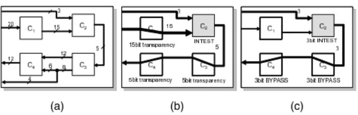
Fig. 1(a) and (b) show an example SoC that the transparency- based methods target and its transparent TAM for core C2, respec- tively. In the previous methods based on transparency, they pro- vided complete transparent access for every functional port shown in Fig. 1(b). Consequently, C2cannot be tested concurrently with the other cores, and only the sequential test is possible. On the other hand, if we use the IEEE 1500 wrapper [14] to test the core, we can select any bit-width of transparent access to test the core in the similar way to the dedicated TAM approaches. Fig. 1(c) shows an example of 3-bit transparent test access to C2. However, C2still cannot be tested concurrently with the other cores even though C1
is free. This is because only the way to propagate the test responses of C1is to pass through C2in the transparency-based TAM design in this example.
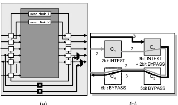
In this paper, we introduce a wrapper configuration that can perform INT ES T and BY PAS S modes simultaneously in order to increase test concurrency in the transparent TAM design effec- tively. Fig. 2(a) shows an example of the proposed wrapper config- uration where INT ES T with 3-bit functional TAM and BY PAS S for 2-bit transparency are realized concurrently. Bypass registers and multiplexers are added not to prevent the core from being tested. By using the proposed wrapper configurations effectively in the transparency-based TAM design, we can increase test con- currency and reduce the overall test time while keeping the area overhead low. For example, we can test C1 and C2concurrently without increasing the SoC functional interconnects by using the proposed wrapper configuration for C2as shown in Fig. 2(b).
3 Problem Formulation
In the dedicated test bus based TAM designs, it is well known that there is a trade-off relation between TAM area and test time.
(a) (b) (c)
Figure 1: (a) An example system S1. (b) Transparent test access for core C2. (c) Transparent test access for C2with 3-bit wrapper.
Design, Automation and Test in Europe (DATE'08), pp. 1366-1369, March, 2008.
(a) (b)
Figure 2: (a) Proposed wrapper configuration (3-bit INT ES T + 2-bit BY PAS S). (b) Concurrent transparent test access for C1and C2. We observe the similar trend in the transparent TAM approach us- ing the proposed wrapper configurations. We can reduce test time by increasing the bit-width of SoC functional interconnects and SoC external I/O ports. However, we consider that the cost for adding extra SoC I/O ports is much higher than that for increas- ing internal interconnects. Therefore, we consider the following optimization problem in this paper.
Definition 1 Popt: Given a set of cores with test parameters, a set of interconnects and maximum allowable increase of interconnects in bit Cmax, determine a wrapper and transparency-based TAM for each core such that: (1) the bit-width of each SoC I/O port and its associated interconnect remains the same, (2) the total increase of interconnects does not exceed Cmax, and (3) the overall test time is minimized.
4 Wrapper and Transparent TAM Co-
Optimization
4.1 ILP Formulation
In this paper, we use the session based test scheduling where test sets are grouped into sessions and new tests are allowed to start only when all tests in the preceding session are completely executed. To solve Popt, for each core k, we decide a test session and a TAM width to test k, and select interconnects used as TAM for k. For each interconnect, the sum of the TAM width used to test cores scheduled in a session is the final TAM width used as TAM in the session. If the final TAM width exceeds the original bit-width of the interconnect, we have to increase the bit-width of it. From the above decisions and selections, finally, we can determine a wrapper configuration for each core in each session to provide the required functionality. We present an ILP formulation to solve Poptas follows.
0-1 Variables:
sj,k: sj,k=1 if core k is tested in session j
rj,k,l: rj,k,l=1 if core k is tested in session j with l bit TAM Integer Variables:
xi, j,k: TAM width on interconnect i to test core k in session j Other Notations:
Ek,in: a set of input interconnects of core k Ek,out: a set of output interconnects of core k w(i) : the original bit-width of interconnect i
time(k, l) : the test time of core k with l bit TAM Constraints:
1. !jsj,k=1 for ∀k, i.e., every core is scheduled in exactly one session
2. !lrj,k,l=sj,kfor ∀ j, k, i.e., every core under test k has exactly one wrapper configuration for INT ES T
3. !i∈Ek,inxi, j,k =!i∈Ek,outxi, j,k =!ll · rj,k,lfor ∀ j, k, i.e., every core under test k has a set of input/output interconnects used as input/output TAM with the width corresponding to the se- lected wrapper configuration
4. !i∈Ek′,inxi, j,k = !i∈Ek′ ,outxi, j,k for ∀ j, k, k′(! k), i.e., if core k′(! core under test k) is used as a part of TAM for k, the sum of the TAM width for k at the input ports of k′is equal to the sum of the TAM width for k at the output ports of k′ (TAM width preservation)
5. maxj
"!
kxi, j,k
#≤w(i) for ∀i associated with SoC I/O ports, i.e., every interconnect associated with an SoC I/O port can- not be increased
6. Cmax ≥ !i
"
max"maxj
"!
kxi, j,k
#,w(i)#−w(i)#, i.e., the total increase of internal interconnect does not exceed Cmax
Objective: Minimize!jmaxk
"!
ltime(k, l) · rj,k,l
#
We can easily include the dedicated test bus design in the pro- posed ILP formulation and consider transparency-based TAM de- sign, dedicated test bus based TAM design and their hybrid TAM design in the proposed ILP formulation.
4.2 Experimental Results for ILP
We made experiments on three SoCs: S1 we handcrafted shown in Fig. 1(a), d695 and p93791 from ITC’02 SOC Test Benchmarks [15]. The test parameters for core C1, C2, C3 and C4in S1are identical to module 1, 5, 6 and 10 in p93791, respec- tively. For d695 and p93791, since the original benchmark SoCs do not have any data on the connectivity between cores, we used randomly-generated interconnects for the SoCs. Table 1 shows the characteristics for the three SoCs. Column 4 denotes the num- ber of SoC I/O bits which can be used as the transparent TAM I/O. Column 5 denotes the number of the dedicated test bus based TAM I/O bits added to the original SoC for comparison purpose.
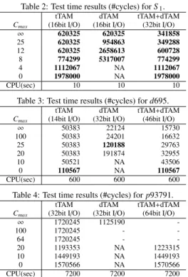
Tables 2, 3 and 4 show the test time results for S1, d695 and p93791, respectively. Columns “tTAM”, “dTAM” and
“tTAM+dTAM” denote the cases where we design the transparent TAM only, the dedicated test buses based TAM only, and their hy- brid TAM, respectively. We used a commercial ILP solver ILOG CPLEX [16] on a SunFireV490 workstation with UltraSPARC IV+ 1.8 GHz processor and 32 GB memory for all the experi- ments. We set the time limit of the ILP solver to 10, 600 and 7200 seconds for S 1, d695 and p93791, respectively. The bold number in the tables means that the ILP solver can reach the optimal solu- tion within the time limit. On the other hand, the non-bold number denotes the best intermediate solution at the time limit. “-” and
“NA” mean that the ILP solver cannot find any intermediate solu- Table 1: Characteristics for three SoCs.
SoC core interconnect tTAM I/O(bits) dTAM I/O(bits)
S1 4 9 16 16
d695∗ 10 20 14 32
p93791∗ 32 52 32 32
Table 2: Test time results (#cycles) for S1.
tTAM dTAM tTAM+dTAM
Cmax (16bit I/O) (16bit I/O) (32bit I/O)
∞ 620325 620325 341858
25 620325 954863 349288
12 620325 2658613 600728
8 774299 5317007 774299
4 1112067 NA 1112067
0 1978000 NA 1978000
CPU(sec) 10 10 10
Table 3: Test time results (#cycles) for d695.
tTAM dTAM tTAM+dTAM
Cmax (14bit I/O) (32bit I/O) (46bit I/O)
∞ 50383 22124 15730
100 50383 24201 16632
25 50383 120188 29763
20 50383 191874 32955
10 50521 NA 43506
0 110567 NA 110567
CPU(sec) 600 600 600
Table 4: Test time results (#cycles) for p93791.
tTAM dTAM tTAM+dTAM
Cmax (32bit I/O) (32bit I/O) (64bit I/O)
∞ 1720245 1125190 -
100 1720245 - -
64 1720245 - -
20 1193353 NA 1223315
10 1449193 NA 1449193
0 1570566 NA 1570566
CPU(sec) 7200 7200 7200
tion within the time limit, and can prove that there is no solution for the given Cmax, respectively.
From the results for small SoC S1 shown in Table 2, we can have the following four observations. First, the ILP solver can get the optimal solution in all cases within 10 seconds. Second, the transparent TAM design can achieve exactly the same test time as the dedicated TAM design when Cmax = ∞. Third, when Cmaxis small, the transparent TAM design can provide much shorter test time compared to the dedicated TAM design by reusing the ex- isting functional interconnect effectively. Finally, we can further reduce the test time by considering both TAM designs simulta- neously during the optimization. For d695, we can observe the similar trend to S1. Especially, even though the bit-width of the I/O ports which can be used in transparent TAM is less than half of that in dedicated TAM, the transparent TAM can provide much shorter test time when Cmax is 25 or below. However, we cannot get the optimal solution in many cases for d695 and all cases for p93791. Moreover, it cannot even find any intermediate solution in some cases for p93791. These results motivated us to present an effective and efficient heuristic approach based on simulated annealing for large SoCs shown in the next section.
5 Heuristic Approach for Wrapper and
Transparent TAM Co-Optimization
5.1 Simulated Annealing
In the previous section, we observed that the proposed ILP model cannot be solved within a reasonable time for large SoCs. Through the experiments, however, we had the following obser- vations: (1) the number of test sessions that gives the minimum test time is much lower than the number of cores (i.e., serial test schedule), and (2) the ILP model can be solved within a few sec- onds once the session assignment for each core is done (i.e., sj,kis decided).
1: Generate an ILP model and an initial session assignment Acur; 2: Solve the ILP with Acurand get the test time Ccur;
3: Set initial temperature T = Tinit; 4: while stop criteria are not met do 5: for i = 1 to Niterdo
6: Generate a neighboring assignment Aneifrom Acur; 7: Solve the ILP with Aneiand get the test time Cnei; 8: ∆C = Cnei−Ccur/*Compute change of cost function*/; 9: if ∆C ≤ 0 then
10: Set Acur=Anei;
11: else
12: Set q = random(0, 1); 13: if q < e−∆C/Tthen 14: Set Acur=Anei;
15: end if
16: end if 17: end for
18: Set new temperature T = β · T ; 19:end while
Figure 3: Simulated annealing algorithm.
Based on the above observations, we present a heuristic method for the wrapper and transparent TAM co-optimization. First, we limit the number of test sessions to a constant value (we used “5” sessions in our experiments). Second, we determine the session assignment for each core outside the ILP model and solve the ILP model with the session assignment. We use the simulated anneal- ing (SA) technique to find the optimum session assignment. The SA algorithm is shown in Fig. 3. The SA algorithm starts to gen- erate an ILP model described in the previous section and solve the ILP model with an randomly generated initial session assignment. Then a neighboring session assignment is randomly created from the current session assignment. If the test time of the neighboring assignment is better than the current assignment, the neighboring assignment is accepted. If the test time of the neighboring assign- ment is not better than the current assignment, it can be accepted at a certain probability which is a function of a parameter referred as temperature. During the optimization process, the temperature is decreased and there is a lower probability of accepting an inferior solution. The optimization process terminates when the tempera- ture reaches the given stop criteria.
5.2 Experimental Results for SA
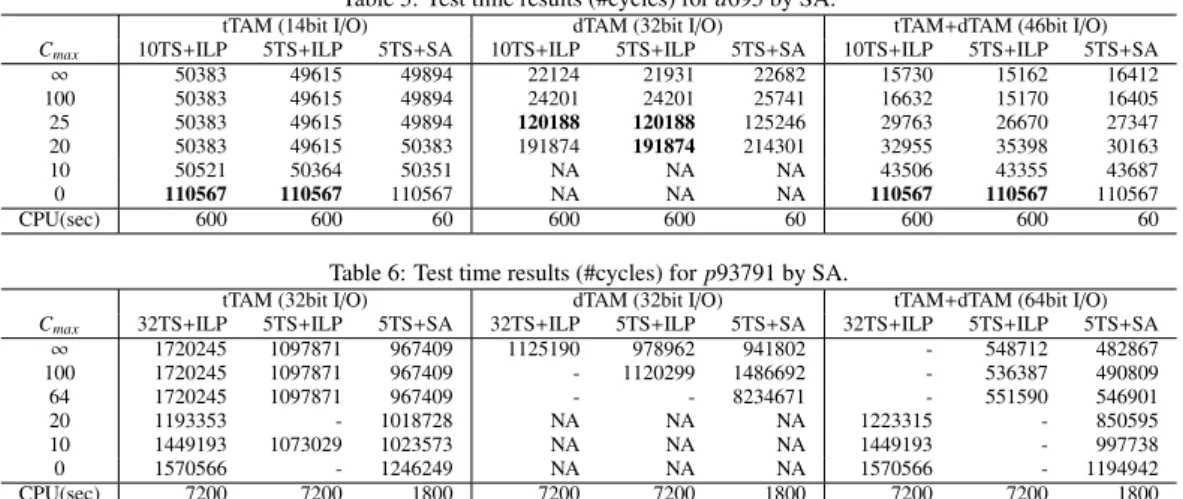
We set the parameters in the proposed SA algorithm so that the computation time for d695 and p93791 become 60 and 1800 seconds, respectively. Tables 5 and 6 show the test time results for d695 and p93719, respectively. Columns 2, 5 and 8 (i.e.,
“10TS+ILP” in Table 5 and “32TS+ILP” in Table 6) denote the test time given by the original ILP model proposed in Section 3. Columns 3, 6 and 9 ,“5TS+ILP”, denote the test time given by the ILP model where the number of test session is limited to five. Columns 4, 7 and 10, “5TS+SA”, denote the test time given by the SA algorithm with 5 test sessions. The number in parentheses de- notes the relative difference from the original ILP model proposed in Section 3.
From the results for d695 shown in Table 5, we observe that the ILP solver can provide slightly better results by limiting the number of test session to 5 in almost all cases. However, it still cannot get the optimal solution for many cases within the given time limit. On the other hand, the proposed SA based approach can achieve approximately the same test time as “5TS+ILP” with 10 times shorter computational time.
For p93791 shown in Table 6, we can get 10 to 36% reduc- tion in test time by limiting the number of test session from 32 to
Table 5: Test time results (#cycles) for d695 by SA.
tTAM (14bit I/O) dTAM (32bit I/O) tTAM+dTAM (46bit I/O)
Cmax 10TS+ILP 5TS+ILP 5TS+SA 10TS+ILP 5TS+ILP 5TS+SA 10TS+ILP 5TS+ILP 5TS+SA
∞ 50383 49615 49894 22124 21931 22682 15730 15162 16412
100 50383 49615 49894 24201 24201 25741 16632 15170 16405
25 50383 49615 49894 120188 120188 125246 29763 26670 27347
20 50383 49615 50383 191874 191874 214301 32955 35398 30163
10 50521 50364 50351 NA NA NA 43506 43355 43687
0 110567 110567 110567 NA NA NA 110567 110567 110567
CPU(sec) 600 600 60 600 600 60 600 600 60
Table 6: Test time results (#cycles) for p93791 by SA.
tTAM (32bit I/O) dTAM (32bit I/O) tTAM+dTAM (64bit I/O)
Cmax 32TS+ILP 5TS+ILP 5TS+SA 32TS+ILP 5TS+ILP 5TS+SA 32TS+ILP 5TS+ILP 5TS+SA
∞ 1720245 1097871 967409 1125190 978962 941802 - 548712 482867
100 1720245 1097871 967409 - 1120299 1486692 - 536387 490809
64 1720245 1097871 967409 - - 8234671 - 551590 546901
20 1193353 - 1018728 NA NA NA 1223315 - 850595
10 1449193 1073029 1023573 NA NA NA 1449193 - 997738
0 1570566 - 1246249 NA NA NA 1570566 - 1194942
CPU(sec) 7200 7200 1800 7200 7200 1800 7200 7200 1800
Table 7: Comparison of test time (#cycles) between the previous transpar- ent TAM and proposed transparent TAM when Cmax= ∞.
SoC tTAM(serial) tTAM(co-opt) red(%)
S1 624066 620325 -0.6
d695 66779 49615 -25.7
p93791 1223481 967409 -20.9
5. However, we cannot get the optimal solution for all the cases. In contrast with the results for d695, the proposed SA based ap- proach can further reduce test time compared to “5TS+ILP” with 4 times shorter computational time. This is because the interme- diate solutions provided by “5TS+ILP” for d695 are very close to the optimal solutions while those for p93791 are still far from the optimal solutions. For the cases such as p93791, the proposed SA based approach can explore the solution space effectively within the limited time compared to the original ILP model proposed in the previous section.
Finally, we compare the proposed wrapper and transparent TAM co-optimization method and the previous transparent TAM methods in Table 7. As we explained in Section 2, the previ- ous transparent TAM methods do not consider the wrapper and TAM co-optimization including test scheduling problem to mini- mize test time. Therefore, only the serial test schedule is possible. Then, we generated the serial test schedule without considering the total increase of interconnects (i.e., Cmax = ∞). In the serial test schedule, we assumed that each core has the maximum wrapper width (i.e., the width of transparent TAM I/O shown in Column 4 of Table 1) for each SoC to minimize the test time. The results for the serial test schedules are shown in Column 2 “tTAM serial” of Table 7. Column 3 “tTAM co-opt” denotes the test time of the proposed method where we chose the best test time among the proposed three approaches (i.e., ILP using complete sessions, ILP using 5 sessions and SA using 5 sessions) when Cmax = ∞. The proposed method can achieve up to 25% reduction in test time.
6 Conclusion
We have proposed an ILP formulation and SA based heuristic approach for wrapper and transparent TAM co-optimization. To the best of our knowledge, the wrapper and transparent TAM co- optimization including test scheduling problem has been discussed for the first time in this paper. We have made experiments on three SoCs where we showed that the proposed ILP model is effective for small SoCs while the SA based heuristic approach can explore
the solution space effectively for large SoCs. The experiments have also shown the effectiveness of the proposed method com- pared to the previous transparent TAM approaches and the con- ventional dedicated TAM approaches.
References
[1] Y. Zorian, E. J. Marinissen, and S. Dey, “Testing embedded-core based system chips,” in Proc. International Test Conference, pp. 130–143, Oct. 1998. [2] V. Iyengar, K. Chakrabarty, and E. J. Marinissen, “Test wrapper and test access
mechanism co-optimization for system-on-chip,” Journal of Electronic Testing: Theory and Applications, vol. 18, pp. 213–230, Apr. 2002.
[3] S. K. Goel and E. J. Marinissen, “Effective and efficient test architecture design for SOC,” in Proc. International Test Conference, pp. 529–538, Oct. 2002. [4] Y. Huang, W. T. Cheng, C. C. Tsai, N. Mukherjee, O. Samman, Y. Zaidan, and
S. M. Reddy, “Resource allocation and test scheduling for concurrent test of core-based SOC design,” in Proc. Asian Test Symposium, pp. 265–270, Nov. 2001.
[5] E. Larsson, K. Arvidsson, H. Fujiwara, and Z. Peng, “Efficient test solutions for core-based designs,” IEEE Trans. Computer-Aided Design, vol. 23, pp. 758– 775, May 2004.
[6] A. Larsson, E. Larsson, P. Eles, and Z. Peng, “Optimization of a bus-based test data transportation mechanism in system-on-chip,” in Proc. Euromicro Confer- ence on Digital Systems Design, pp. 403–409, Sep. 2005.
[7] F. A. Hussin, T. Yoneda, A. Orailoglu, and H. Fujiwara, “Power-constrained SOC test schedules through utilization of functional buses,” in Proc. Interna- tional Conference on Computer Design, pp. 230–236, Oct. 2006.
[8] E. Cota, M. Kreutz, C. A. Zeferino, L. Carro, M. Lubaszewski, and A. Susin,
“The impact of NoC reuse on the testing of core-based systems,” in Proc. VLSI Test Symposium, pp. 128–133, Apr. 2003.
[9] C. Liu, Z. Link, and D. Pradhan, “Reuse-based test access and integrated test scheduling for network-on-chip,” in Proc. Design, Automation, and Test in Eu- rope, pp. 303–308, Mar. 2006.
[10] M. Nourani and C. A. Papachristou, “Structural fault testing of embedded cores using pipelining,” Journal of Electronic Testing:Theory and Applications, vol. 15, pp. 129–144, Aut.–Oct. 1999.
[11] S. Ravi, G. Lakshminarayana, and N. K. Jha, “Testing of core-based systems- on-a-chip,” IEEE Trans. Computer-Aided Design, vol. 20, pp. 426–439, Mar. 2001.
[12] K. Chakrabarty, “A synthesis-for-transparency approach for hierarchical and system-on-a-chip test,” IEEE Trans. VLSI Systems, vol. 11, pp. 167–179, Apr. 2003.
[13] T. Yoneda, A. Shuto, H. Ichihara, T. Inoue, and H. Fujiwara, “TAM design and optimization for transparency-based SoC test,” in Proc. VLSI Test Symposium, pp. 381–386, May 2007.
[14] “IEEE standard testability method for embedded core-based integrated cir- cuits.” IEEE Std 1500-2005, 2005.
[15] E. J. Marinissen, V. Iyengar, and K. Chakrabarty, “A set of benchmarks for modular testing of SOCs,” in Proc. International Test Conference, pp. 519–528, Oct. 2002.
[16] ILOG, Inc., “CPLEX 9.0 Reference Manual,” Dec. 2003.