An SoC Test Scheduling Algorithm using Reconfigurable Union Wrappers
Tomokazu Yoneda†, Masahiro Imanishi† and Hideo Fujiwara†
†Graduate School of Information Science, Nara Institute of Science and Technology
Kansai Science City, 630-0192, Japan
{yoneda, fujiwara}@is.naist.jp
Abstract
This paper presents a reconfigurable union wrapper that can wrap multiple cores into a single wrapper design. Moreover, we present a test scheduling algorithm to min- imize a test application time using the proposed reconfig- urable union wrapper. The proposed heuristic algorithm can achieve short test application time with low computa- tional cost compared to the conventional approaches where every core has its own wrapper. Experimental results for the ITC’02 SOC Benchmarks show the effectiveness of our approach.
keywords: system-on-a-chip, test scheduling, reconfig- urable union wrapper, test access mechanism
1 Introduction
In the SoC test environment, each embedded core is iso- lated from other logics during test of the core. Therefore, the following three components are necessary for SoC test- ing: 1) test pattern source and test response sink, 2) test access mechanism (TAM), and 3) wrapper [1]. The TAM propagates test patterns for a core from test pattern source to the core, and furthermore propagates the responses from the core to test pattern sink. The wrapper provides func- tions for cores to switch the mode of the cores: 1) nor- mal, 2) INTEST, 3) EXTEST, and 4) BYPASS defined in IEEE 1500 standard [2]. The goal for SoC test is to develop techniques for wrapper design, TAM design and test sched- ule that minimizes test application time under given con- straints. A number of approaches have addressed wrapper design [3, 4, 5]. Several TAM architectures have been pro- posed such as TestBus [6, 7], TESTRAIL [8], transparency based TAMs [9, 10, 11]. However, wrapper and TAM co-optimization problem was shown to be NP-hard in [3]. Therefore, many heuristic approaches for this problem have been proposed [4, 5, 12, 13, 14, 15, 16, 17].
Recently, the reconfigurable wrapper was proposed by Koranne [18] that allows a core to have several wrapper configurations in contrast to the previous approaches. The advantage is the increased flexibility for the test schedul- ing. Larsson and Peng proposed the reconfigurable power- conscious core test wrapper to increase the flexibility for power-constrained test scheduling [19].
One crucial aspect of these approaches including recon-
figurable and non-reconfigurable wrapper designs is that each core has an own wrapper and a core is tested inde- pendently of other cores. Quasem et al. showed that further reductions in test application time can be achieved if mul- tiple cores are wrapped into single wrapper design and the overlapped test application scheme is used [20]. They also proposed the reconfigurable wrapper design that includes all embedded cores in a single wrapper. In the proposed reconfigurable wrapper design, the length of each wrapper scan chain can be reconfigured (reduced) during test by by- passing scan chains which are not necessary for further test application.
However, wrapping all the cores into a single wrapper design cannot alway achieve the minimum test application time due to the lack of flexibility for test scheduling. More- over, the proposed reconfigurable wrapper can only bypass scan chains in each wrapper scan chain, and cannot re- assign scan chains to different wrapper scan chains.
This paper presents a reconfigurable union wrapper that can wrap multiple cores into a single wrapper design. More- over, we present a test scheduling algorithm to minimize a test application time using the proposed reconfigurable union wrapper. The proposed algorithm finds the optimal core groups for designing reconfigurable union wrappers, and it can achieve short test application time with low com- putational cost. Experimental results for the ITC’02 SOC Benchmarks show the effectiveness of our approach.
The rest of this paper is organized as follows. We dis- cuss our motivation in Section 2. Section 3 shows a recon- figurable union wrapper design. After formulating a test scheduling problem using reconfigurable union wrappers in Section 4, we present a test scheduling algorithm in Section 5. Experimental results are discussed in Section 6. Finally, Section 7 concludes this paper.
2 Motivation
In this section, we examine the effectiveness of the re- configurable union wrapperfor minimizing test application time by using example cores shown in Fig.1. A significant amount of research has been devoted to reducing test ap- plication time. Consequently, several test scheduling algo- rithms have been proposed. In these approaches, every core has its own wrapper and cores are tested independently of
1
Design, Automation and Test in Europe (DATE'07), pp. 231-236, April 2007.
Figure 1. Wrapper designs using three wrapper scan chains by [3].
others by using the wrappers. Wrapper designs for core 1 and 2 using three wrapper scan chains are shown in Fig.1(a) and Fig.1(b), respectively. The time required to apply the entire test set to a core is given as follows.
T =(1 + max{si,so}) · p + min{si,so} (1) Here, p is the number of test patterns, and si(so) is the length of the longest wrapper scan-in(scan-out) chain for the core. In this example, test time for core 1 and core 2 are 550 and 605, respectively. The total test time for these two cores is 1165 if core 1 and core 2 are tested serially by using a shared TAM with three bits.
Fig.2 shows the proposed reconfigurable union wrap- per design for core 1 and core 2. The wrapper design has two test configurations. The first configuration shown in Fig.2(b) includes all scan chains, and core 1 and core 2 are tested at the same time for first 50 patterns. After applying the first 50 patterns, the wrapper is reconfigured to config- uration 2 shown in Fig.2(c) where only scan chains in core 2 are connected to the wrapper scan chains. Then, core 2 is tested using configuration 2 for the remaining 50 patterns. Test time for configuration 1 and 2 are 560 and 305, re- spectively. The total test time for these two cores is 860 since the first scan-in in configuration 2 can be overlapped with the last scan-out in configuration 1. Consequently, we can achieve 26% test time reduction by using the proposed reconfigurable union wrapper. Therefore, we can reduce the total SoC test time if we can find the optimal groups for the proposed reconfigurable union wrappers during test scheduling.
3 Reconfigurable Union Wrapper Design
In this section, we present a method to design the recon- figurable union wrapper. Let S be the set of cores and w be the number of wrapper scan chains. The proposed proce- dure is shown in Fig.3. First, configuration ID i is set to 1Figure 2. A reconfigurable union wrapper and its configurations.
(line 1). Then, configuration i is designed by WrapperDe- signprocedures proposed in [3] by regarding cores in S as a single core (line 3). After that, the cores with the small- est number of test patterns are removed from S (line 4), and configuration ID i is increased by 1 (line 5). The above pro- cess is repeated until S becomes empty. An example of the reconfigurable union wrapper for core 1 and core 2 shown in Fig.1 and its configurations are shown in Fig.2.
procedure RUW(S, w) 1 i := 1;
2 while(S! φ){
3 design configuration i by WrapperDesign in [3] for S; 4 S:= S - {c} s.t.
chas the smallest number of test patterns in S; 5 i:= i + 1;
6 }
Figure 3. Reconfigurable union wrapper design procedure.
4 Problem Formulation
From our preliminary experiments, we observed that we cannot always achieve minimum test time by uniting all cores in a given SoC into one group and giving one pro- posed reconfigurable wrapper to them. The total SoC test time can be reduced if we can find the optimal groups for the proposed reconfigurable union wrappers during test scheduling. Therefore, we formulate the test scheduling problem using reconfigurable union wrappers as follows. Definition 1 Pruw: Given the maximum TAM width Wmax, a set of cores M and for each core m ∈ M the test set pa- rameters including the number of test patterns pm, the num- ber of input terminals im, the number of output terminals om, the number of bidirectional terminals bm, the number of scan chains sm and for each scan chain k the length of it lm,k, determine the test groups, the TAM width and the
reconfigurable union wrapper design for each group, and a test schedule such that: (1) the total number of TAM wires utilized at any moment does not exceed Wmax and (2) the overall test time is minimized.
5 Scheduling Algorithm using Reconfig-
urable Union Wrapper
In this section, we present an algorithm for determining a solution to the test scheduling problem using reconfigurable union wrappers. In our algorithm, a TAM b is represented as a set of cores which are connected to b. Our algorithm determines a solution which consists of
• the set of TAMs B such that every core is assigned to exactly one TAM,
• the width w(b) of every TAM b ∈ B such that the summed widths of the TAMs does not exceed Wmax,
• the reconfigurable union wrapper design for each TAM b ∈ B
such that total test time T is minimized. To determine the test time t(b, w) for a TAM b with width w, we assume the existence of a procedure TestTime(b,w) which use a proce- dure RUW(b,w) for designing a reconfigurable union wrap- per for cores in b presented in Section 3.
An outline of this algorithm is presented in Fig.4. The al- gorithm is inspired by an existing effective algorithm (TR- Architect[14]), and it has three main steps which are AS- SIGN, TRANSFER and MERGE.
procedure TestSchedule
1 sort M in the descending order based on the amount of test data; 2 for all m ∈ M in the decided order at line1{
3 ASSIGN(m); 4 TRANSFER(); 5 }
6 repeat until no more improvement on T is possible{ 7 MERGE();
8 TRANSFER(); 9 }
Figure 4. Scheduling algorithm
First, it sorts cores in the descending order based on the amount of test data (line 1). The amount of test data of a core is equivalent to the test time provided by the wrapper design using one wrapper scan chain. Then, a core is as- signed to a TAM such that current total test time T is min- imized by ASSIGN procedure (line 3). Whenever a core is assigned, TRANSFER procedure is executed (line 4). The TRANSFERprocedure tries to minimize T by finding a bot- tleneck TAM bmaxwhich is a TAM with the longest test time and re-assigning a core in bmaxto other TAM. TRANSFER repeats the above process until no more improvement on T is possible. After assigning all cores to TAMs, the algorithm performs the MERGE procedure (line 7). The MERGE pro- cedure tries to minimize T by finding a bottleneck TAM bmax and merging bmax with other TAM. MERGE repeats
the above process until no more improvement on T is possi- ble. Then, the TRANSFER procedure is executed again (line 8). These MERGE and TRANSFER procedures are repeated until no more improvement on T is possible. Each of these steps is explained in more detail in the sequel of this section. 5.1 Assignment
The procedure ASSIGN as outlined in Fig.5 determines a TAM to which the current targeted core m is assigned. It consists of three main steps.
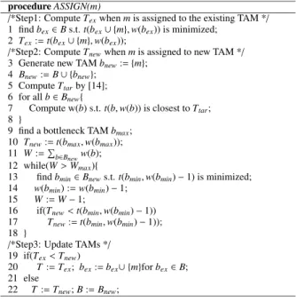
procedure ASSIGN(m)
/*Step1: Compute Texwhen m is assigned to the existing TAM */ 1 find bex∈Bs.t. t(bex∪{m}, w(bex)) is minimized;
2 Tex:= t(bex∪{m}, w(bex));
/*Step2: Compute Tnewwhen m is assigned to new TAM */ 3 Generate new TAM bnew:= {m};
4 Bnew:= B ∪ {bnew}; 5 Compute Ttarby [14]; 6 for all b ∈ Bnew{
7 Compute w(b) s.t. t(b, w(b)) is closest to Ttar; 8 }
9 find a bottleneck TAM bmax; 10 Tnew:= t(bmax,w(bmax)); 11 W :=!b∈B
neww(b);
12 while(W > Wmax){
13 find bmin∈Bnews.t. t(bmin,w(bmin) − 1) is minimized; 14 w(bmin) := w(bmin) − 1;
15 W:= W − 1;
16 if(Tnew<t(bmin,w(bmin) − 1)) 17 Tnew:= t(bmin,w(bmin) − 1)); 18 }
/*Step3: Update TAMs */ 19 if(Tex<Tnew)
20 T:= Tex; bex:= bex∪{m}for bex∈B; 21 else
22 T:= Tnew; B := Bnew;
Figure 5.ASSIGNprocedure
In Step 1 (line 1-2), for each TAM b ∈ B which already exists in the current test schedule, it computes the test time when the core m is assigned to b and a reconfigurable union wrapper for b is designed. Then, it finds bexwhich is a TAM with the shortest test time Texafter assigning m. In Step 2 (line 3-18), it computes the test time Tnewwhen a new TAM bnew is created and the core m is assigned to bnew. When bnew is created, for each TAM b ∈ B ∪ bnew, the width of b is updated such that test time of b is the closest to the lower bound Ttaron test time proposed in [14] for the cores currently scheduled (line 6-8). Consequently, if the total TAM width W exceeds Wmax, the algorithm finds a TAM bminsuch that t(bmin,w(bmin) − 1) is minimized and the TAM width w(bmin) is updated. This process is repeated until W does not exceed Wmax(line 12-18). In Step 3 (line 19-22), two solutions created in Step 1 and 2 are compared and the solution with smaller test time is selected.
Fig.6 shows an example of the ASSIGN procedure. In this example, it tries to assign core 4 for the current test schedule shown in Fig.6(a). Fig.6(b) and (c) show the re- sults of Step 1 and 2, respectively. Consequently, core 4 is
Figure 6. An example ofASSIGNprocedure. assigned to TAM 2 since the solution shown in Fig.6(b) has smaller test time.
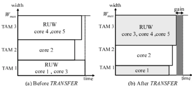
5.2 Transfer
The procedure TRANSFER as outlined in Fig.7 tries to minimize the total test time T by finding a bottleneck TAM bmaxand re-assigning a core in bmaxto other TAM.
procedure TRANSFER()
1 repeat until no more improvement on T is possible{ 2 Find a bottleneck TAM bmax;
3 Tmax:= t(bmax,w(bmax)); 4 for all core s ∈ bmax{ 5 for all TAM b ∈ B − {bmax} { 6 Ttemp:= ∞;
7 b1:= b ∪ {s}; b2:= bmax−{s}; 8 wb1:= w(b1); wb2:= w(b2);
9 repeat until no more improvement on Ttempis possible{ 10 if(Ttemp>max(t(b1,wb1+1), t(b2,wb2−1))){ 11 Ttemp:= max(t(b1,wb1+1), t(b2,wb1−1)); 12 wb1:= wb1+1; wb2:= wb2−1;
13 }
14 }
15 if(Ttemp<Tmax){
16 Tmax:= Ttemp; bmin:= b; smin:= s; 17 wb1,new:= wb1; wb2,new:= wb2;
18 }
19 }
20 }
21 if(Tmax<T){
22 bmin:= bmin∪{smin}; bmax:= bmax−{smin}; 23 w(bmin) := wb1,new; w(bmax) := wb2,new; 24 T:= Tmax;
25 }
26 }
Figure 7.TRANSFERprocedure
First, it finds a bottleneck TAM bmax and computes its test time Tmax (line 2-3). Then, for each core s ∈ bmax, it computes the test time Ttemp when s is removed from bmax and re-assigned to other TAM b ∈ B − {bmax}(line
Figure 8. An example ofTRANSFERprocedure. 4-20). During this step, TAM width of bmaxis also reduced from bmaxand re-assigned to b until no more improvement on Ttempis possible (line 9-14). After that, it finds a core smin∈bmaxand bmin ∈B − {bmax}such that test time Ttemp
is minimized when sminis re-assigned to bmin(line 15-20). If the re-assignment gives smaller test time than T which is the current total test time, then it updates the solution. TRANSFER repeats the above reassignment until no more improvement on T is possible.
Fig.8 shows an example of the TRANSFER procedure. In this example, core 3 in the bottleneck TAM 1 is re-assigned to TAM 3 and a part of width of TAM 1 is also re-assigned to TAM 3.
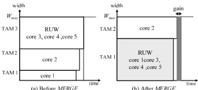
5.3 Merge
The procedure MERGE as outlined in Fig.9 tries to min- imize the total test time T by finding the bottleneck TAM bmaxand merging bmaxwith other TAM.
procedure MERGE()
1 repeat until no more improvement on T is possible{ 2 Find a bottleneck TAM bmax;
3 Tmax:= t(bmax,w(bmax)); 4 for all b ∈ B − {bmax} { 5 btemp:= b ∪ bmax; 6 wtemp:= w(b) + w(bmax); 7 if(t(btemp,wtemp) < Tmax){ 8 Tmax:= t(btemp,wtemp); bmin:= b;
9 }
10 }
11 if(T > Tmax){
12 w(bmin) := w(bmin) + w(bmax); 13 bmin:= bmin∪bmax; 14 B:= B − {bmax} 15 T:= Tmax;
16 }
17 }
Figure 9.MERGEprocedure
First, it finds a bottleneck TAM bmax and computes its test time Tmax(line 2-3). Then, for each core b ∈ B − {bmax}, it computes the test time when bmaxis merged with b (line 4-10). After that, it finds a TAM bmin ∈ B − {bmax}such that test time Tmaxis minimized when bmaxis merged with bmin (line 15-20). If the merged TAM gives smaller test time than the current total test time T , then it updates the
Figure 10. An example ofMERGEprocedure.
solution. MERGE repeats the above process until no more improvement on T is possible.
Fig.10 shows an example of the MERGE procedure. In this example, the bottleneck TAM 3 is merged with TAM 1.
6 Experimental Results
Table 1 compares the test time results obtained using the proposed method with those using the test scheduling meth- ods proposed by Im et al. [5], Xia et al. [16] and Zou et al. [4]. We have chosen the methods presented in [5, 16, 4] for comparison since they have been applied to the ITC’02 benchmarks [21] and give the best results to the best of our knowledge. Here, we considered the ITC’02 benchmarks SoCs to be flat. In 23 out of the 28 cases (7 TAM widths for 4 benchmarks) our method can find the solution with the smallest test time.
In Table 1, we also show the lower bound on test time proposed in [14] in order to discuss the potential advantage of the proposed reconfigurable union wrapper. We can ob- serve that our method finds the solution with smaller test time than the lower bound in some cases. It should be noted that the lower bound of the test time proposed in [14] is computed assuming that every core has its own wrapper and tested independently of other cores. From these results, we can say that test time can be reduced further than the lower bound by using the proposed reconfigurable union wrapper where multiple cores have a single wrapper and are tested at the same time.
In terms of area overhead, the proposed reconfigurable union wrapper needs additional multiplexers for changing its configurations. Table 2 shows the area overhead com- puted by the following equation.
overhead =
!(gates of additional multiplexers)
!(gates of 1500 wrapper cells) ×100 (2) Please note that the area overhead is only to the logic intro- duced by IEEE 1500 wrapper cells, not to the overall SoC. In other words, the area overhead shows the increase ratio for each wrapper cell. The number of wrapper cells de- pend only on the number of I/O cells of the cores and do not depend on the number of gates of the cores. Therefore,
for complex cores with hundreds of thousands of gates, this overhead will become insignificant.
7 Conclusion
In this paper we have proposed a reconfigurable union wrapper and a test scheduling algorithm using it. We have shown that by allowing multiple cores to have a single wrap- per, test time can be reduced compared to the approaches where every core has its own wrapper. Moreover, our method finds the solution with smaller test time than lower bound proposed in [14] in some cases. This indicates the potential advantage of the proposed reconfigurable union wrapper for test time minimization.
Acknowledgments
This work was supported in part by Japan Society for the Promotion of Science (JSPS) under Grants-in-Aid for Sci- entific Research B(No. 15300018) and for Young Scientists B(No.18700046). The authors would like to thank Profs. Kewal K. Saluja, Michiko Inoue, Dr. Satoshi Ohtake and members of Fujiwara Laboratory (Nara Institute of Science and Technology) for their valuable comments.
References
[1] Y. Zorian, E. J. Marinissen and S. Dey,“Testing embedded- core based system chips,” Proc. IEEE International Test Conference, pp. 130–143, Oct. 1998.
[2] E. J. Marinissen, R. Kapur, M. Lousberg, T. McLaurin, M. Ricchetti and Y. Zorian, “On IEEE P1500’s Standard for Embedded Core Test,” Journal of Electronic Testing: The- ory and Applications, pp. 365–383, Aug. 2002.
[3] V. Iyengar, K. Chakrabarty and E. J. Marinissen, “Test Wrapper and test access mechanism co-optimization for system-on-chip,” Journal of Electronic Testing: Theory and Applications, pp. 213–230, Apr. 2002.
[4] W. Zou, S. R. Reddy, I. Pomeranz and Y. Huang,“SOC Test Scheduling Using Simulated Annealing,” Proc. 21th VLSI Test Symposium, pp. 325–329, May 2003.
[5] J. Im, S. Chun, G. Kim, J. An and S. Kang, “RAIN(RAndom INsertion) Scheduling Algorithm for SoC Test, ” Proc. IEEE 13th Asian Test Symposium, pp. 242–247, Nov. 2004. [6] T. Ono, K. Wakui, H. Hikima, Y. Nakamura and M. Yoshida,
“Integrated and automated design-for-testability implemen- tation for cell-based ICs,” Proc. 6th Asian Test Symposium, pp. 122–125, Nov. 1997.
[7] P. Varma and S. Bhatia, “A structured test re-use methodol- ogy for core-based system chips,” Proc. IEEE International Test Conference, pp. 294–302, Oct. 1998.
[8] E. Marinissen, R. Arendsen, G. Bos, H. Dingemanse, M. Lousberg and C. Wouters, “A structured and scalable mech- anism for test access to embedded reusable cores,” Proc. IEEE International Test Conference, pp. 284–293, Oct. 1998.
Table 1. Test time results (#cycles). Wmax
soc approach 16 24 32 40 48 56 64
our method 40933 27456 20789 16935 14144 11978 10571
RA[5] 41442 27725 20948 16852 14182 12084 10628
d695 EA[16] 41553 27982 21014 16908 14240 11988 10571
SA[4] 41604 28064 21161 16993 14182 12085 10723
Lower Bound[14] 40951 27305 20482 16388 13695 11709 10247 our method 420299 283391 214434 169891 143756 123721 114579 RA[5] 422345 284632 214354 173637 145781 126548 112620
p22810 EA[16] 438783 292824 226545 167792 153260 133094 117638
SA[4] 438619 289287 218855 175946 147944 126947 109591 Lower Bound[14] 419466 279644 209734 167787 139823 119848 104868 our method 924846 625963 544579 544579 544579 544579 544579 RA[5] 939855 625543 544579 544579 544579 544579 544579
p34392 EA[16] 939855 641514 544579 544579 544579 544579 544579
SA[4] 944768 628602 544579 544579 544579 544579 544579 Lower Bound[14] 932790 621903 544579 544579 544579 544579 544579 our method 1739032 1157239 868825 696522 580936 500200 438141 RA[5] 1742995 1157974 870059 701204 587907 500976 441786 p93791 EA[16] 1754980 1171190 886038 706820 600986 501057 445748 SA[4] 1754452 1169945 878493 718005 594575 509041 447974 Lower Bound[14] 1746657 1164442 873334 698670 582227 499053 436673
Table 2. Area overhead (%) to IEEE wrapper cells. Wmax
soc 16 24 32 40 48 56 64
d695 33.84 28.82 32.98 27.65 21.26 22.55 29.62 p22810 23.16 35.41 25.47 31.47 32.68 37.53 38.82
p34392 5.84 3.75 2.43 2.43 2.43 2.43 2.43
p93791 109.42 114.38 96.90 128.88 159.88 136.33 86.46
[9] M. Nourani and C. A. Papachristou, “Structural fault test- ing of embedded cores using pipelining,” Journal of Elec- tronic Testing:Theory and Applications 15(1-2), pp. 129– 144, Aug.–Oct. 1999.
[10] S. Ravi, G. Lakshminarayana, and N. K. Jha, “ Testing of core-based systems-on-a-chip,” IEEE Trans. on CAD, Vol. 20, No. 3, pp. 426–439, Mar. 2001.
[11] T. Yoneda, T. Uchiyama and H. Fujiwara, “Area and time co-optimization for system-on-a-chip based on consecutive testability,” Proc. IEEE International Test Conference, pp. 415–422, Sep. 2003.
[12] Y. Huang, W. T. Cheng, C. C. Tsai, N. Mukherjee, O. Sam- man, Y. Zaidan and S. M. Reddy,“Resource allocation and test scheduling for concurrent test of core-based SOC de- sign,” Proc. Asian Test Symposium, pp. 265-270, Nov. 2001. [13] V. Iyengar, K. Chakrabarty and E. J. Marinissen, “On using rectangle packing for SOC wrapper/TAM co-optimization,” Proc. 20th VLSI Test Symposium, pp. 253–258, Apr. 2002. [14] S. K. Goel and E. J. Marinissen,“Effective and Efficient Test
Architecture Design for SOCs,” Proc. IEEE International Test Conference, pp. 529-538, Oct. 2002.
[15] Y. Huang, N. Mukherjee, S. Reddy, C. Tsai, W. Cheng, O. Samman, P. Reuter and Y. Zaidan, “Optimal core wrap- per width selection and SOC test scheduling based on 3- dimensional bin packing algorithm,” Proc. IEEE Interna-
tional Test Conference, pp. 74–82, Oct. 2002.
[16] Y. Xia, M. C. Jeske, B. Wang and M. Jeske, “Using Dis- tributed Rectangle Bin-Packing Approach for Core-based SoC Test Scheduling with Power Constraints, ” IEEE/ACM 2003 International Conference on Computer-Aided Design, pp. 100–105, Nov. 2003.
[17] E. Larsson, K. Arvidsson, H. Fujiwara and Z. Peng,“Efficient Test Solutions for Core-based De- signs,”IEEE Trans. on CAD, Vol. 23, No. 5, pp. 758–775, May 2004.
[18] S. Koranne, “A Novel Reconfigurable Wrapper for Testing of Embedded Core-Based SOCs and its Associated Schedul- ing Algorithm, ” Journal of Electronic Testing:Theory and Applications, Vol. 18(4/5), pp. 415–434, 2002.
[19] E. Larsson and Z. Peng, “A Reconfigurable Power- Conscious Core Wrapper and its Application to SOC Test Scheduling, ” Proc. IEEE International Test Conference, pp. 1135–1144, Sep. 2003.
[20] Md. S. Quasem and S. Gupta, “Designing Reconfigurable Multiple Scan Chains for Systems-on-Chip, ” Proc. 22th IEEE VLSI Test Symposium, pp. 365–371, Apr. 2004. [21] E. J. Marinissen, V. Iyengar and K. Chakrabarty, “A Set of
Benchmarks for Modular Testing of SOCs,” Proc. IEEE In- ternational Test Conference, pp. 519–528, Oct. 2002.
![Figure 1. Wrapper designs using three wrapper scan chains by [3].](https://thumb-ap.123doks.com/thumbv2/123deta/5752811.27055/2.892.453.787.183.419/figure-wrapper-designs-using-wrapper-scan-chains.webp)
![Table 1. Test time results (#cycles). W max soc approach 16 24 32 40 48 56 64 our method 40933 27456 20789 16935 14144 11978 10571 RA[5] 41442 27725 20948 16852 14182 12084 10628 d695 EA[16] 41553 27982 21014 16908 14240 11988 10571 SA[4] 41604 28064 21161](https://thumb-ap.123doks.com/thumbv2/123deta/5752811.27055/6.892.150.718.179.681/table-test-time-results-cycles-max-approach-method.webp)
