Compressing Test Data for Deterministic BIST Using a
Reconfigurable Scan Architecture *
Dong Xiang Yang Zhao Krishnendu Chakrabarty Jiaguang Sun
School of Software, Dept. of Comput. Sci. and Tech., Dept. Elec. and Comp. Eng., School of Software
Tsinghua University, Tsinghua University Duke University Tsinghua University
Beijing 100084, China Beijing 100084, China Durham, NC 27708, USA Beijing 100084, China [email protected] [email protected] [email protected] [email protected]
Hideo Fujiwara Grad. School of Inform. Sci., Nara Institute of Sci. and Techn.
Ikoma, Nara 630-0101, Japan [email protected]
Abstract
-
We present a new scan-based BIST tech- nique, which is based on weighted scan enable signals and a scan forest architecture. A new testability measure is pro- posed t o guide test pattern generation and produce pat- terns with fewer specified bits. This approach can effec- tively reduce the amount test data that needs t o be stored on-chip. The proposed BIST method relies on a pseude random phase and a deterministic phase. The scan forest architecture is configured as a single scan tree for deter- ministic test vector application in the second phase. It is found that an LFSR with size equal t o the maximum num- ber of the specified bits in the deterministic patterns for the random-resistant faults is sufficient to encode deter- ministic vectors for the benchmark circuits. Experimental results for benchmark circuits demonstrate the effedive- ness of the proposed method.Keywords -Deterministic BIST, scan-based BIST, scan forest, testing with weighted scan enable signal.
The test length for scan-based built-in self-test (BIST) is usually determined by the random-pattern-resistant (hard-to-detect) faults. Test length reduction for the hard- to-detect faults is therefore an important practical prob- lem. Various techniques have been developed t o handle this problem. The most popular techniques include: (1) weighted random testing [3]; (2) test point insertion [18]; (3) deterministic scan-based BIST. The test application time is also an important issue for scan-based BIST.
Weighted random testing refers t o the application of test patterns derived using primary inputs with signal probabilities that are different from 0.5 [3]. This technique helps us to reduce test length, and thereby the test appli- cation time needed to reach high fault coverage. Weighted random testing schemes must store multiple sets of weights in most cases, and multiple test sessions are necessary [7]. Weighted random testing schemes with multiple test ses- sions require complex control logic [7].
It has been shown that the use of parallel scan chains alone may not be sufficient to obtain high fault coverage with low test time (3, 81. A well-designed phase shifter
(PS) has been shown to increase the fault coverage [15]. However, this approach typically requires a large number of (short) scan chains, as well as area overhead for the PS and a multiple-input signature-register (MISR). Usu- ally, the number of stages in the pseudo-random test pat- tern generator (PRTG) is fixed, and a well designed phase shifter [15] can be used to avoid interdependences among the outputs of the PRTG. The storage requirement for a deterministic BIST method with a well-designed PS can however still be very Iarge [8, 14, 161.
It is therefore necessary to design a more efficient pseudo-random test generator. It is well-known that weighted pseudo-random test pattern generation can in- crease fault coverage for pseudo-random testing. How- ever, weighted random testing methods in use today apply weighted vectors only to the primary inputs. None of these methods that can generate weighted vectors for the pseudo- primary inputs without modifying the scan flip-flops.
Deterministic scan-based BIST schemes usually utilize the large number of unspecified bits in deterministic test vectors. As shown by Koenemann [lo], deterministic test vectors can be encoded into LFSR seeds, whose size equals the maximum number of specified bits S,,, in the deter- ministic test vectors plus 20. The requirement on the size of the LFSR can be reduced to S,,,
+
4 by using multi- ple primitive polynomials [5, 61. Efficient test generation techniques have been presented to reduce the number of specified bits in the deterministic test vectors [6], and test vector concatenation has been proposed to encode multi- ple patterns with a single seed. Rajski et al. [16] improved encoding efficiency by using variant-length seeds and mul- tiple primitive polynomials. Krishna, Jas, and Touba [ l l ] proposed a new test encoding scheme based on the loading of seeds with size less than the LFSR size; this method incrementally modifies the next seed in the process of test application.Recently, a test encoding scheme with multiple primi- tive polynomials and various ranks was proposed t o com- press deterministic test data [9]. Seed ordering and seed encoding were used to reduce storage requirement in [2], where the test vector concatenation technique was im- proved significantly. The states of the circuit in separate clock cvcles. instead of the state after the shift cycles of " ,
'This work was partially supported by the National Science separate test cycles, can be used t o encode determiaG-+;-- Foundation of China under grants 60373009 and 60425203. test vectors. Li and Chakrabarty [13] proposed a reco
l ? f l
15th Asian Test Symposium (ATS'O6)
COMPUTER
15th IEEE Asian Test Symposium (ATS'06), pp. 299-304, November 2006.
combinational eircuiu
Figure 1: Weighted scan enable signals for scan-forest- based BIST.
urable scan architecture to improve the encoding efficiency of deterministic BIST, where the interconnections between the outputs of the LFSR and the inputs of the scan chains can be dynamically reconfigured.
In this paper, we propose a new scan-based BIST scheme based on the scan forest architecture and weighted scan enable signals. The proposed BIST method relies on a pseudorandom phase and a deterministic phase. The scan forest is reconfigured into a scan tree in the determin- istic BIST phase. The proposed method applies different weights to the scan enable signals of all scan segments. The proposed pseudo-random testing scheme can significantly improve fault coverage in the first phase. A new testabil- ity measure is proposed to guide test generation such that test patterns with fewer specified bits are obtained. For all benchmark circuits, the proposed method is able to encode all deterministic vectors using an LFSR whose size is equal to the maximum number of specified bits in a test pattern. The rest of this paper is organized as follows. The scan- BIST architecture based on a reconfigurable scan forest is described in Section 2. The new scan architecture using a scan forest and weighted scan enable signals is introduced in Section 3. A new testability measure is introduced to guide test generation for test vectors with fewer specified bits in Section 4. Experimental results are given in Section 5. Section 6 concludes the paper.
11. THE RECONFIGURABLE SCAN ARCHITECTURE
FOR DETERMINISTIC BIST
In this section, we describe the scan-based architecture for the proposed two-phase BIST method. As shown in Figure 1, the scan forest architecture is used for pseudo- random testing in the first phase. Each stage of the phase shifter (PS) drives multiple scan segments, where all scan flip-flops at the same stage for all scan segments are driven by the same stage of the phase shifter. The test response compactor is an XOR gate network. Two scan segments (al, az, . .
.,
a,) and (bl, b2,.
..,
bn) are connected to the same XOR gate if the scan flip-flop pairs ( a l , bl), (az, bz), ..
., and (a,, b,) do not have any common combinational predecessor.Unlike the conventional test-per-scan BIST scheme, each scan segment is driven by a separate scan enable sig- nal. We use the set of weights {0.5,0.625,0.75,0.875) to control the scan enable signals. In the pseudo-random test-
'-'
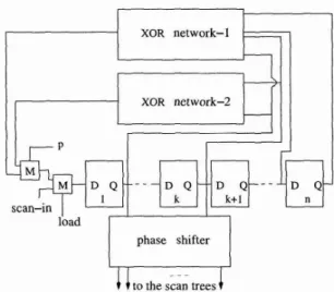
to the scan treesFigure 2: The linear-feedback shift-register design for t h e two phases.
ing phase, the primary inputs are directly driven by the phase shifter. Each of the primary inputs is driven by a scan flip-flop of a scan segment in the deterministic BIST phase. The primary inputs are also grouped with all the scan flip-flops. A primary input (PI) can be included into a scan flip-flop group if P I does not have any combinational successor with any of the scan flip-flops in the group. Let the scan flip-flops in the group be a t the kth level of the scan tree. The P I in that group can be driven by any scan flip-flop a t the (k
-
1)th level in the scan tree. This can be implemented by using a multiplexer for each primary input as shown in Figure 1, where the multiplexer is controlled by the signal p. The phase shifter is connected t o the pri- mary input when p = 0 (pseudo-random testing phase), and the primary input is connected to a scan tree when p = 1 (deterministic BIST phase).Usually, a small LFSR is sufficient when a well de- signed phase shifter is adopted in the pseudo-random test- ing phase. In our method, a combination of a 24-stage LFSR and the phase shifter from [15] is used to gener- ate test patterns in the pseudo-random testing phase. The size of the LFSR needed for deterministic BIST depends on the maximum number of specified bits for any determinis- tic test vector. While two different LFSRs can be used for the two phases, a composite LFSR design can be used as shown in Figure 2. The same signal p as the one presented in Figure 1 is used to switch between two XOR feeback net- works. The XOR network-1 is used for the pseudo-random testing phase, while the XOR network-2 is used for the de- terministic BIST phase. All seeds stored in the ROM are shifted in from the scan-in signal. The overhead needed t o implement the LFSR with two polynomials involves only one additional XOR network and a multiplexer. Only a few two input XOR gates are needed if a primitive polynomial with very few terms is used to generate pseudo-random test vectors.
The phase shifter drives the scan trees and primary in- puts only in the pseudo-random testing phase. The scan forest architecture is reconfigured to a single scan tree dur- ing the deterministic BIST phase, where all primary inputs are driven by some internal scan flip-flops in order t c
--
duce the number of test inputs and the number of specQ
15th Asian Test Symposium (ATS'OG)0-7695-2628-4106 $20.00 O 2006
IEEE COMPUTER
SOCIETYL
L F- - - S R1 1 !
X ,1
phase shifteri
- - -
----if--, - -
-compactor
1 1
- - -I
I
multiple input signature registerI
Figure 3: The reconfigurable scan architecture for pseudo-random testing a n d deterministic BIST.
bits in the deterministic test vectors for the hard faults. As shown in Figure 3, one extra multiplexer is inserted before the scan-in signal of each scan tree. The signal p is used for test phase selection, and it is the same as in Figure 1 and Figure 2. The pseudo-random testing phase corresponds to p = 0, and the deterministic BIST phase is used when when p = 1. The scan trees receive test signals from the phase shifter during the pseudo-random testing phase.
In t h ~ d~terministic BIST phase, the scan tree receives test vectors from the scan-in signal of the rightmost scan tree; see Figure 3. The scan-in signal of the rightmost scan tree is connected t o a stage of the LFSR directly in the deterministic BIST phase. The dashed lines shown in Figure 3 connect the scan-in signals of the scan trees with output of the last scan flip-flop in one of the scan segments in its right scan tree. The outputs of all scan segments are still connected to the compactor during the deterministic BIST phase; this offers additional flexibility for test encod- ing. The test responses of the previous test vector can be shifted out with only a few clock cycles (corresponding to the depth of the scan forest in the pseudo-random testing phase). For a single scan chain architecture, the number of clock cycles needed to shift out test responses of the previ- ous deterministic test vector is much more-it equals the number of scan flip-flops in the circuit.
An effective seed encoding scheme is used here to reduce the storage requirements for the deterministic test patterns for the random-resistant faults. The test responses of each test vector are shifted out with k clock cycles (k is the depth of the scan forest). The test responses are captured again when the state of the scanned circuit is compatible with any other deterministic test vector.
111. SCAN-BASED BIST USING SCAN FOREST AND
WEIGHTED SCAN ENABLE SIGNALS The i-controllability Cf(1) (i E {0,1)) of a node I is defined as the probability that a randomly selected input 15th Asian Test Symposium (ATS'O6)
P test
PPO PPl "
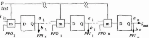
Figure 4:
A
scan segment with a weighted scan enable signal.vector sets 1 to the value i. The observability 01(1) is de- fined as the probability that a randomly selected input vector propagates the value of I to a primary output. The signal probability of a node is defined in the same manner as its 1-controllability measure.
In the scan-based architecture as shown in Figure 1, dif- ferent weights el, e z ,
. .
., and ek are assigned t o the scan en- able signals of the scan segments SCI , SC2,. .
., and SCk, respectively, where e l , ez, ..
., ek E {0.5,0.625,0.75,0.875). We do not assign weights values less than 0.5 to the scan enable signals because we do not want to insert more cap- ture cycles than scan shift cycles. We have developed an efficient method to select weights for the scan enable sig- nals of the scan segments. The selection of weights for the scan enable signals is determined by the following testabil- ity gain function:where l/i represents the stuck-at i (i E ( 0 , l ) ) fault at line I . In Equation ( I ) , F is the random-resistant fault set, defined as the set of faults whose detection probability is no more than 10 times that of the hardest fault [3]. Note that our method does not consider redundant faults according to the COP measure [4] when selecting weights. We attempt to minimize the testability gain function as given in Equation (1).
Figure 4 presents a scan chain with a weighted scan enable signal, where Sin, S,,t and test are the scan-in sig- nal, scan-out signal, and the scan enable signal of the scan chain, respectively. Initially, all pseudo-primary inputs are assigned signal probability 0.5, and the observability of the pseudo-primary outputs is set to l/n. Let p be the selected weight of the scan enable signal as shown in Figure 4. Then
The observability of P P O i can be estimated as follows:
We set the observability of the scan-out signal t o 1. Even though the output of a scan segment is connected to the test response compactor, we can make the alias- ing negligible by carefully connecting the scan segments to the XOR gates as described in Section 11. We also have Of(an) = 1 and Cb(Sin) =C:(Sin) = 0.5. Testability mea- sures of the internal nodes and PPIs and PPOs can be calculated iteratively using the COP measures and Equa- tions (2)-(5). We find that the testability measures fo-
-"
nodes in the benchmakr circuits converge quickly.
Q
COMPUTER
As shown in Figure 2, the BIST control logic assigns weighted signals to the scan enable signals. In functional mode, the extra pin test is assigned value 0. The circuit is set to the test mode when test is set to value 1. In this case, the selected weight is assigned t o a scan chain. The scan chain works in the shift mode when the weighted scan enable signal is 1, and works under the capture mode when the scan enable signal is set t o value 0. The weighted signals are produced by a phase shifter, the details of which is presented later in this section. Only one extra pin is necessary in the scan-based BIST design.
We assume that each scan segment uses separate scan enable signals. We assign weights from the set (0.5, 0.625,0.75,0.875) t o the scan enable signals of the scan segments. In the weight selection procedure, S is the scan segment set and SC is a specific scan segment. Initially, S contains all scan segments in the circuit. The procedure t o determine weights can be described as follows: First, all scan segments use the regular test-per-scan scan enable signals. That is, scan enable signals are set to 1 in scan shift cycles and set to 0 in capture cycles. A test cycle for the original scan enable signals contains k scan shift cycles followed by one capture cycle, where k is the length of the longest scan segment. Our method selects a weight for the first scan segment scan enable signal t o minimize the gain function. After the best weight has been selected for the first scan segment, we select aweight for the scan enable signal of the second scan segment that minimizes the cost function in Equation (1). For each scan segment, if no weight can be selected, we leave its scan enable sig- nal as the one in conventional test-per-scan BIST scheme (the number of shift cycles is equal t o the length of the scan segments, and a capture cycle follows). Continue the above process until appropriate weights have been chosen for all scan enable signals of the scan segments. Further details to select weights for the scan enable signals can be found from [20].
Different weights can be obtained by connecting two or more pseudo-random signals 131. As shown in Figure 3, all weights are connected to a multiplexer which is con- trolled by the signal p. The selected weight is connected to the scan enable signal of the scan segment when p = 0 in the pseudo-random testing phase. The signal test2 is connected to the scan enable signals of all scan segments during the deterministic BIST phase, where the scan forest is reconfigured as a scan tree (i.e., d shift cycles followed by a capture cycle, where d is the depth of the scan tree in the deterministic BIST phase).
IV. TESTABILITY MEASURE TO GUIDE TEST PATTERN GENERATION WITH FEWER
SPECIFIED BITS
All pseudo-primary inputs (PPIs) corresponding t o the same scan flip-flop group are merged into a single PPI. As shown in Figure 1, each of the primary inputs shares the same PPI with the scan flip-flops in the same group. This technique reduces the number of test inputs, and it also reduces the number of specified bits in the deterministic test vectors for the hard faults left after the pseudo-random testing phase.
We next present another simple SCOAP-like testabil- ity measure to guide test pattern generation such that we obtain test vectors with even fewer specified bits. We in- 15th Asian Test Symposium (ATS'O6)
0-7695-2628-4106 $20.00 O 2006 IEEE
troduce the following additional definitions. Let RCi(1) be defined as the minimum set of primary inputs (or pseudo- primary inputs) that have to be fixed t o a logic value in order to set line I to value i, where i E { 0 , l ). The control- lability Ci (1) is defined as the minimum number of primary inputs (or pseudo-primary inputs) that must be assigned specified values in order to place control value i E {O,l) on line I. Let I be a primary input. We have
RCI ( P I ) = RCo(PI) = {PI), (6)
c,
(PI) = c o ( P I ) = 1. (7) For an AND gate 1 with inputs A and B , we haveRC1 ( I ) = RCI (A) U RCi (B), (8) Ci (I) = JRCi (I)]. (9) where IRCl (I)( is the size of the set RCl (1). We also have RCo(1) = RCo(A) if (RCo(A)(
<
(RCo(B)I, RCo(2) = RCo(B) if IRCo(A)l>
IRCo(B)J. For an OR gate I with inputs A and B,We have R 4 (1) = RCi (A) if IRCI (A)]
<
IRC1 (B)I, RC1 (I) = RC1 (B) if IRCI (A)\>
IRC1(B)17 andFor a fanout s with branches BI, Bz,
.
..,
B k , for i E { O , l ) , and j E: {1,2,.. .,
k), we have:The controllability calculation of the testability measure for other gates is similar. The function RO(1) is defined as the smallest set of primary inputs (or pseudo-primary inputs) that need to be assigned specified values in order to propagate the fault effect at I either t o a primary output or t o a pseudo-primary output. The observability O(1) is defined as the minimum number of primary inputs (or pseudo-primary inputs) that need to be assigned specified values in order to propagate the fault effect a t I to either to a primary output or to a pseudo-primary output. For a primary output (or a pseudo-primary output) I, we have O(1) = 0 and RO(1) = 0. Consider an AND gate 1 with inputs A and B, we have
RO(A) = RO(1) U RCi (B), (13)
O(A) = IRO(A)I. (14)
Let I be the output of an OR gate with inputs A and B. We have:
Let s be a fanout stem with fanout branches B1, Bz, ., B k . In this case, the following relationships hold:
The observability cdculation for other gate types is -;-
ilar. Let l/i be a single stuck-at fault at I for i E
{a
, l l F
COMPUTER
SOCIETY
We define the detectability D ( l / i ) as the minimum num- ber of primary inputs (pseudo-primary inputs) that need to be assigned specified values in order to generate a test pattern for the fault. Therefore,
The above testability measure is used to guide test genera- tion for test vectors with fewer specified bits. For example, any one of the inputs can be assigned to value 0 in order to set the output of a 2-input AND gate t o value 0. Our method selects the input with less 0-controllability in this case. A fault effect at a fanout stem can be propagated along any fanout branch. Our method selects the fanout branch with the least observability.
A well-designed LFSR must be used in order to encode all deterministic vectors after the pseudo-random testing phase. A new scheme is presented to select a primitive polynomial with the minimum degree that can encode all deterministic test vectors for the hard faults. Let the max- imum number of the specified bits of the deterministic vec- tors be Sm,,. This process continues until a primitive polynomial that encodes all deterministic test vectors is found. Experiments show that deterministic vectors for the hard faults for all benchmark circuits can be encoded by a primitive polynomial with degree equal to S,,,.
The test responses of a deterministic test vector must be shifted out using L clock cycles, where L is the number of scan flip-flops in the longest scan chain. The reconfig- urable scan architecture as shown in Fig. 3 offers flexibility for seed encoding for the deterministic vectors. The test responses captured by the scan flip-flops can be shifted out in only L1 clock cycles, where L1 is the depth of the scan forest in the pseudo-random testing phase. Our method uses up to 215 shift cycles to cover more deterministic pat- terns between the period to load two seeds. The seed of a new test vector with the most number of specified bits is next selected to be loaded into the LFSR.
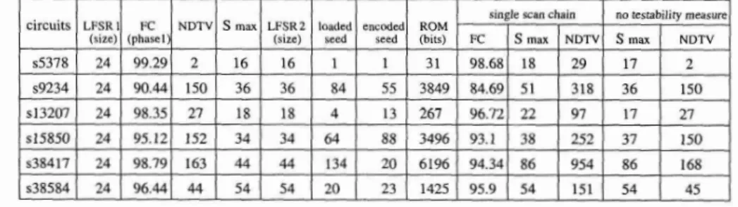
The proposed BIST method has been implemented and experiments have been carried out using a Sun Blade2000 workstation. Table 1 presents results for the largest IS- CAS89 benchmark circuits. The ATALANTA test gen- erator [12] is used to generate deterministic test vectors of the hard faults. LFSRl and LFSR2 denote the sizes of the LFSR in the pseudo-random testing and the deter- ministic BIST phases, respectively. Column 3 presents the fault coverage of the proposed pseudo-random test gen- eration scheme after 500K clock cycles. The parameters NDTV, S,,,, and ROM (bits) denote the number of de- terministic test vectors, the maximum number of specified bits in the deterministic test patterns, and the number of bits that need to be stored on-chip in a ROM. The three columns with the single scan chain list the fault coverage, the maximum number of specified bits in the deterministic test patterns, and the number of deterministic test vectors for the hard faults after 10000 pseudo-random test pat- terns are applied. The CPU time to do fault simulation for the 10000 pseudo-random test patterns needs much more than 1 day for the largest ISCAS89 benchmark circuits, such as, s38417 and s38584 while the CPU time based 011
the weighted scan enable signal based test scheme is only 15th Asian Test Symposium (ATS'O6)
about one hour. More pseudo-random test patterns for the pseudo-random test scheme with a single scan chain can- not get any fault coverage increment for almost all circuits. The last two columns in Table 1 show the performance of the deterministic test generator without using the new testability measure.
The results in Table 1 show that the scan forest archi- tecture and the primary input merging scheme can signif- icantly reduce the maximum number of specified bits in many cases. The proposed testability measure can further reduce the maximum number of specified bits in the test vectors to detect the hard faults for circuits s5378, ~15850, and ~38417. I t is particularly noteworthy that the new testability measure can reduce the maximum number of specified bits in the deterministic test vectors from 86 t o 44 for ~38417. It is also seen that the proposed pseudo- random testing scheme with weighted scan enable signals can significantly increase the ifault coverage of the first phase for almost all circuits. We compare our method t o a single scan chain a 10000 pseudo-random test vectors. It is shown that the proposed scan forest architecture with weighted scan enable signals can improve fault coverage significantly, especially for s9234 and ~38417. Therefore, the proposed new pseudo-random testing scheme can re- duce deterministic data volume considerably.
We next compare our method several previously publsi- hed methods, namely Koe. [lo], MP [5], variant-length [16], SO [2] (seed ordering), FAST [14], partial [Ill, and VLMP [9]. Table 2 presents the sizes of the LFSRs and the test data volumes for all methods. The proposed method obtains the least test data volume for all circuits using LFSR with the least size. For every circuit, we are able to encode all deterministic test vectors for the hard faults using an LFSR of size equal t o the maximum number of specified bits in the deterministic test vectors. We can attribute this observation t o two reasons: (1) The pseudo- random test generator is highly efficient, and most hard faults that need more specified bits are detected in Phase 1; (2) selection of a proper primitive polynomial.
VI. CONCLUSIONS
We have presented a new BIST method that is based on a scan forest architecture and weighted scan enable signals for all the scan segments. The weighted scan enable signals are used to apply pseudorandom patterns in the first phase of the BIST procedure. The scan forest architecture is con- figured as a single scan tree in the second (deterministic) phase. A simple composite LFSR design is used to derive two different LFSRs for the two test phases. A new testa- bility measure is proposed to generate deterministic test vectors with fewer specified bits for the hard faults. Ex- perimental results have been presented for the benchmark circuits, and we have shown that the proposed method out- performs a number of competing BIST and compression techniques. We have also shown that for the bechmark circuits, the determinstic patterns can be generated using an LFSR whose size is equal to the maximum number of specified bits in these patterns.
[I] V. D. Agrawal, C. R. Kime, and K. K Saluja. " A
tutorial on built-in self-test, part 1: principles," I.
, , p p
COMPUTER
Table 1: Results obtained for t h e largest ISCAS89 circuits using t h e proposed BIST method.
r
single scan chain no testability measure circuits LFSRl FC NDTV S max LFSRZ loaded encoded ROM .
(size) (phasel) (size) seed seed (hits) FC S max NDTV S max N D W
s5378 24 99.29 2 16 16 1 1 31 98.68 18 29 17 2
Design and Test, vol. 10, no. 1, pp. 73-82, 1993. [2] A. A. Al-Yamani, S. Mitra, and E. J. McCluskey,
&'Optimized reseeding by seed ordering and encoding," IEEE Trans. on CAD, vol. 24, no. 2, pp. 264-270, 2005.
[3] P. H. Bardell, W. H. McAnney, and J. Savir, Built- in Test for VLSI: Pseudo-Random Techniques, New York: Wiley, 1987.
[4] F. Brglez, "On testability of combinational networks," Proc. of IEEE ISCAS, pp. 221-225, 1984.
[5] S. Hellebrand, J. Rajski, S. Tarnick, S. Venkatara- man, and B. Courtois, "Built-in test for circuits with scan based on reseeding of multiple polynomial linear feedback shift registers," IEEE Trans. on Computers, vol. 44, no. 2, pp. 223-233, 1995.
[6] S. Hellebrand, B. Reed, S. Tarnick, H. J. Wunder- lich, "Pattern generation for a deterministic BIST scheme," Proc. of IEEE/ACM ICCAD, pp. 88-94, 1995.
[7] R. Kapur, S. Patil, T. J. Snethen, and T. W. Williams,
"A weighted random pattern test generation system," IEEE Trans. on CAD, vol. 15, pp. 1020-1025, 1996. [8] G. Kiefer and H. J. Wunderlich, "Deterministic BIST
with multiple scan chains," Proc. of IEEE ITC, pp. 1057-1064, 2000.
(91 H. S. Kim, Y. Kim, and S. Kang, "Test decompression mechanism using a variable length multiple polyno- mial LFSR," IEEE Bans. on VLSI Systems, vol. 11, no. 4, pp. 687-690, 2003.
[lo] B. Koenemann, "LFSR-coded test patterns for scan designs," Proc. of ETC, pp. 237-242, 1991.
[ l l ] C. V. Krishna, A. Jas, and N. Touba, ''Achieving high encoding efficiency with partial dynamic LFSR re- seeding," ACM Trans. on Design Automatzon of Elec- tronic Systems, vol. 9, no. 4, pp. 500-516, 2004. 15th Asian Test Symposium (ATS'O6)
0-7695-2628-4106 $20.00 O 2006 IEEE
[12] H. K. Lee and D. S. Ha, "On the generation of test patterns for combinational circuits," Technical report 12-93, Dept. of Electrical Eng., Virginia Polytechnic Institute and State University.
[13] L. Li and K. Chakrabarty, "Test set embedding for deterministic BIST using a reconfigurable intercon- nection network," IEEE Trans. CAD, vol. 23, no. 9, pp. 1289-1305, 2004.
[14] N. Oh, R. Kapur, and T. W. Williams, ''Fast seed computation for reseeding shift register in test pattern compression," Proc. of IEEE/ACM ICCAD, pp. 76- 81, 2002.
[15] J. Rajski, N. Tamarapalli, and J. Tyszer, "Automated synthesis of large phase shifters for built-in self-test," Pmc. of IEEE ITC, pp. 1047-1056, 1998.
[16] J. Rajski, J. Tyszer, and N. Zacharia, "Test data de- compression for multiple scan designs with bound- ary scan," IEEE Trans. Computers, vol. 47, no. 11, pp. 1188-1200, 1998.
[17] H. C. Tsai, K. T. Cheng, and S. Bhawmik, "On improving test quality of scan-based BIST," IEEE
Trans. CAD, vol. 19, no. 8, pp. 928-938, 2000. [18] D. Xiang, M. J. Chen, J. G. Sun, and H. Fujiwara,
"Improving test effectiveness of scan-based BIST us- ing scan chain partitioning," IEEE Trans. on CAD, vol. 24, no.6, pp. 916-927, June, 2005.
[19] D. Xiang, S. Gu, J. Su, and Y. Wu, "A cost-effective scan architecture for scan testing with non-scan test power and test application cost," Proc. of ACM/IEEE DAC, pp. 744-747, 2003.
[20] D. Xiang, M. J. Chen, and H. Fujiwara, "Using weighted scan enable signals to improve the effective- ness of scan-based BIST," Proc. of 14th IEEE ATS, pp. 126-131, 2005.
C ~ M P U T E R SOCIETY