Max-Testable Class of Sequential Circuits having Combinational Test
Generation Complexity
Debesh Kumar Das1, Tomoo Inoue2, Susanta Chakraborty3, and Hideo Fujiwara4
1Computer Sci. & Eng. Dept., Jadavpur University, Calcutta -700 032, India, [email protected]
2
Faculty of Information Sciences, Hiroshima City University, Japan, [email protected]
3
Computer Sci. Dept., Kalyani University, West Bengal, India, [email protected]
4 Graduate School of Inf. Science, Nara Institute of Science and Technology, [email protected] Abstract: The paper uses the concept of time expansion model [9] to find the test generation for acyclic sequential circuits. It identifies a class of sequential circuits called as max-testable sequential circuits, where test generation can be obtained using a combinational test generator with the capability of detecting multiple faults on a kernel of combinational circuit. Any acyclic sequential circuit without hold registers belongs to this class. For the sequential circuits having hold registers, a subset of such circuits are found to be belonged to max-testable class. The paper also suggests an algorithm to find such class of circuits.
1. Introduction
Test generation for a sequential circuit is, in general a hard problem and may be unsolvable in reasonable amount of time for a large circuit [1],[2]. If a test generation problem of a sequential circuit S can be reduced to the problem of test generation for a combinational circuit, then S is called a sequential circuit with combinational test generation complexity [3]. Generally, it is believed that the cyclic structures of sequential circuits are mainly responsible for making the test generation of such circuits more complex. But even acyclic sequential circuits do not allow test generation with combinational test generation complexity. Several attempts were reported earlier to find the classes of acyclic sequential circuits that can provide combinational test generation complexity. For example, strongly balanced [4], balanced [5], internally balanced [6] are classes of circuit structure with this feature.
If the acyclic sequential circuit contains hold registers, the situation becomes worse for the test generation. In [7], a concept of time expansion graph (TEG) was introduced for testing of acyclic sequential circuits, where test generation is done using a combinational test generator on a combinational kernel circuit called as time expansion model (TEM). In this method all the hold registers are scanned. The concept of this model was later enriched in [8],[9] and attempts were made to find the test generation by not scanning the hold registers.
In this paper we use the concept of TEG and TEM and explore the properties of TEG, which lead us to identify a class of acyclic sequential circuits called as max-testable class for which test generation can be obtained by running a combinational test generator with capability of detecting multiple faults on a combinational kernel.
This class includes (i) all acyclic sequential circuits without hold registers and (ii) a subset of sequential circuits containing hold registers. We also present an algorithm to search for such class of circuits.
2. Preliminaries
2.1 Time Expansion Graph (TEG)
Definition 1: (Topology graph) A topology graph is a directed graph G = (V,A,r), where a vertex v∈ V denotes a logic block and an arc (u, v) ∈A denotes a connection from u to v and each arc has a label r: A → Z+ (non-negative integers) ∪ {h}.When two logic blocks u,v are connected through one or more L-registers, the label r(u,v) denotes the number of L-registers (i.e., r(u,v) → Z+). When two logic blocks u,v are connected through one hold register, the label r(u,v) =h.
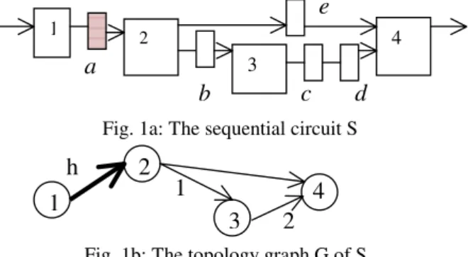
Example 1: Consider a sequential circuit S shown in Fig. 1a, in which 1,2,3 and 4 are logic blocks, b,c,d, and e, are L-registers, and a which is highlighted, is a H-register. The topology graph G of S is shown in Fig. 1b.
Definition 2: The set of direct predecessors of any vertex u in a directed graph is denoted as pre(u). The set of direct successors of any vertex u in a directed graph is denoted as suc(u).
1 2
3
4 a
c d
b
Fig. 1a: The sequential circuit S
1
2
3
4
h 1
2 Fig. 1b: The topology graph G of S
e IEEE 13th Asian Test Symposium (ATS'04), pp. 342-247, Nov. 2004.
Definition 3: (Time-expansion graph (TEG)): Let S be an acyclic sequential circuit and let G=(V,A,r) be the topology graph of S. Let E=(VE, AE, t, l) be a directed graph, where VE is a set of vertices, AE is a set of arcs, t is a mapping from VE to a set of integers, and l is a mapping from VE to the set of vertices in G. If graph E satisfies the following five conditions, graph E is said to be a time-expansion graph (TEG) of G.
C1(Logic Preservation) The mapping l is a surjective, i.e., ∀v ∈V, ∃u ∈VE s.t. v = l(u) C2(Input preservation) Let u be a vertex in E. For any direct predecessor v (∈pre(l(u)) of l(u) in G, there exists a vertex u’ in E such that l(u’) = v and u’∈ pre(u).
C3(Time consistency) For any arc (u,v) ( ∈AE), there exists a corresponding arc (l(u),l(v)), and if r(l(u),l(v)) ∈Z+, then r(l(u),l(v))=t(v)-t(u), or else (r(l(u),l(v))=h, t(u) < t(v).
C4(time uniqueness) For any pair of vertices u,v (
∈VE), if t(u) = t(v) and if l(u) =l(v), then the vertices u and v are identical, i.e., u=v.
C5(Hold consistency) For any pair of arcs (u1,v1), (u2,v2) (∈ AE) such that (l(u1), l(v1)) = (l(u2), l(v2)) and r(l(u1), l(v1)) = r(l(u2), l(v2)) = h, if t(v1) > t(v2), then either t(u1) = t(u2) or t(u1) > t(v2). Example 2: Figs. 2a, 2b and 2c show the three TEGs E1, E2 and E3 respectively of the TG G shown in Fig. 1b.
Remark: Note that TEGs E1 and E2 are different only in time-frames – they are isomorph to each other. From now on, we consider them as same. Lemma 1: Given two TEGs E1 ( V1, A1,t1,l1) and E2
( V2, A2,t2,l2) of a TG G (V,A,r), let u1∈ V1and u2
∈V2 are two vertices in E1 and E2 respectively such that l1(u1) = l2(u2). Then for any vertex v1∈ pre( u1), there exists a vertex v2∈ pre( u2), such that l1(v1) = l2(v2).
Proof: See [10].
Lemma 2: Let G= (V,A,r) be the TG of an acyclic sequential circuit S, and let E = (VE, AE, t, l) be a TEG of G. Consider two vertices v1 and v2∈ VE, such that l(v1) =l(v2) = w ∈V. If there exists a vertex u ∈VE such that (l(u),w) and u ∈pre(v2), then (l(u),w) is a hold arc in the TG G.
Proof: see [10].
Lemma 3: Given two vertices u and v in a TEG, all paths between them are having same length.
2.2 Time Expansion Model (TEM)
Definition 4: [9] Let S be an acyclic sequential circuit, let G= (V,A,r) be the topology graph of S, and let E=( VE, AE,t,l) be a TEG of G. The combinational circuit CE(S) obtained by the following procedure is said to be the time- expansion model (TEM) of S based on E.
(1) For each vertex u ∈ VE, let logic block l(u) (∈V) be the logic block corresponding to u. (2) For each arc (u,v)∈ AE, connect the output of u to the input of v with a bus in the same way as (l(u),l(v)) (∈A). Note that the connection corresponding to (u,v) has noregister even if the connection corresponding to (l(u),l(v)) has a register (i.e., r(l(u),l(v)) ≠0).
(3) In each logic block, lines and logics that are reachable to neither other ogic blocks nor primary outputs are removed.
Example 3: Fig. 3 is a TEM of the sequential circuit S (Fig. 1a) based on TEG E1 (Fig. 2a). Theorem 1: [9] Let S be an acylic sequential circuit, and let F be the set of faults in S. Let G
=(V,A,r) be the topology graph of S.
(1) A fault f ∈ F is testable (or irredundant) in S if and only if there exists a TEG E of G such that the fault fe∈ Fe,corresponding to f is testable in the TEM CE(S) based on E.
(2) A test pattern for a fault fe (∈ Fe) obtained using a TEM CE(S) can be transformed into a test sequence for the fault f (∈ F) corresponding to fault fe.
From this theorem, we can see that test generation for an acyclic sequential circuit can be performed by using several different TEMs. Furthermore, since TEMs are fully combinational, a combinational test generator can be used for the test generation provided the test generator can deal with the multiple faults.
2.3 Cover relation
Given a TG, there can be several TEGs for it. Fig. 2a: TEG of G: E1 Fig. 2b: TEG of G: E2
2 1
4 2 1 3
1 3 4 1
2
Fig.3: TEM of S based on E1
2 1
4 2 1 3
2 1
4 2 3
Fig. 2c: TEG of G: E3
2
Definition 5: A vertex in a directed graph is called as a sink vertex, if there is no outgoing edge from the vertex.
Example 4: The vertex 4 in each of the directed graphs of Figs. 1b, 2a, 2b and 2c is a sink vertex.. Definition 6: Let u is a vertex in TG G and let E(VE, AE, t, l) be any TEG of G. The cone sub- graph E’ (E, u) of E with respect to u is defined as the maximal sub-graph of E in which uE [l(uE) = u] is the only sink vertex, i.e. there is no other vertex vE in E’, for which l(vE)=u.
Definition 7: Let G = (V, A, r) be the TG of an acyclic sequential circuit S, and let E1 = (V1, A1, t1, l1) and E2 = (V2, A2, t2, l2) be arbitrary TEGs of G. Let s be any sink vertex in G. Let E’1(E1,s) = (V’1, A’1) [E’2(E2,s) = (V’2, A’2)] is the cone sub-graph of E1 [E2] with respect to s. TEG E1 is said to cover TEG E2 if there exists a mapping m from V’1 to V’2, such that for every s,
(i) m(s1) = s2, where l1(s1)= l2(s2) =s (ii) For v1 ∈ V’1 and v2 ∈ V’2, if v2 =
m(v1), then the following condition holds, for any pair of vertices u1 ∈ pre(v1) and u2∈ pre(v2), if l1(u1) = l2(u2), then u2=m(u1).
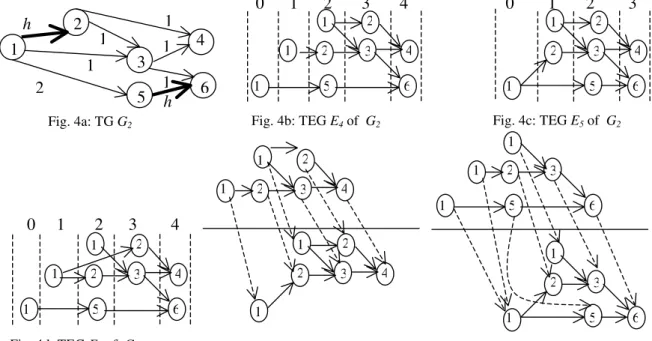
Example 5: Consider the TG G2 of Fig. 4a. The three TEGs of G2, E4, E5 and E6 are shown in Figs. 4b, 4c and 4d respectively. E4 covers E5 with the mapping shown. Notice that E4 does not cover E6. Example 6: The TEG E1 (Fig. 2a) and E2 (Fig. 2b) covers TEG E3(Fig. 2c). Obviously, E1 (Fig. 2a) covers E2 and E2covers E1
Definition 8: Given a TG, if there exist two TEGs E1 and E2 for it such that E1 covers E2 and E2
covers E1, then E1 and E2 are said to be equivalent. Example 7: E1 (Fig. 2a) and E2 (Fig.2b) are equivalent.
Remark: If the two TEGs are equivalent, they are not necessarily isomorph to each other.
The question is, given two TEGs E1 and E2 for a TG G, how to determine that whether E1 covers E2. The answer is, we have to find the mapping m, if exists as defined in Definition 7. The following algorithm determines the cover relation by finding the required mapping.
Algorithm Cover-relation (G,E1,E2)
Input: TG G(V, A, r), TEG E1(V1, A1, t1, l1), TEG E2(V2, A2, t2, l2)
Output: to find mapping m if E1 covers E2, else report “NO COVER”
for every sink vertex s∈V
(1) select vertex s1∈ V1and s2∈ V2, such that l1 (s1) =l2 (s2)= s,
Let E’1(E1,s) = (V’1, A’1) and E’2(E2,s) = (V’2, A’2) be cone sub-graphs with respect to s. Make m(s1) = s2, mark s1 as mapped
(2) for each vertex u2 [u2∈V’2]that has a mapping relation m(u1)=u2, where u1 (∈V’1) is already mapped.
for each vertex v2∈ pre(u2)
(a) find a vertex v1∈ pre(u1) with l1(v1)
= l2(v2).
(b) if such v1 is already mapped, then (i) report “NO COVER”
(ii) return else (i) make m(v1)= v2,
(ii) mark v1 as mapped
1
2
3
4
h 1
1 1
5 1h 6 2
1
2 1
4 2 1 3
1 5 6
2 1
4 2 1 3
2 1
4 2 3 1
2 1
3
1 5 6
2 3
1 5 6
1 Fig. 4a: TG G2
0 1 2 3 4
Fig. 4d: TEG E6 of G2 Fig. 4e: The mapping m that showing the covering of E5 by E4
1 2
1
4 2 1 3
1 5 6
2 1
4 2 3
1 5 6
0 1 2 3 4 0 1 2 3
Fig. 4b: TEG E4 of G2 Fig. 4c: TEG E5 of G2
Lemma 4: The algorithm cover-relation establishes the cover relation between two TEGs, if it exists. Proof: see [10].
Lemma 5: Let G= (V, A, r) be the TG of an acyclic sequential circuit S, and let E1 = (V1, A1, t1, l1) and E2 = (V2, A2, t2, l2) be arbitrary TEGs of G, where E1 covers E2 with a mapping m. Let s1 and s2 be any two sink vertices in E1 and E2 respectively, such that l1(s1) = l2(s2). Let E’1 = (V’1, A’1, t’1, l’1) [E’2 = (V’2, A’2, t’2, l’2)] is the cone sub-graph of E1[E2] with s1[s2] as sink vertex. If v1 and v2 are two non-sink vertices in V’1 and V’2 respectively, such that, v2 = m(v1), then U2(v2)⊇U1(v1), where Ui(vi) is a set of vertices in TG G given by Ui(vi) = {v∈ V !v = li(u), u∈suc(vi)}.
Proof: see [10].
Definition 9: A path from a vertex u1 to uk in a TG G(V, A, r) [TEG E(VE, AE, t, l)] is obtained by concatenation of several arcs (u1,u2), (u2,u3), (u3,u4), (u4,u5),…….,(uk-1,uk) ∀ i, 1< i < (k-1), where (ui, ui+1)∈A [AE].
Definition 10: Given a TG G(V,A,r) let E(VE, AE, t, l) be any TEG of it, let p be a path from a vertex u1
to uk in E obtained by concatenation of the arcs (u1,u2), (u2,u3), (u3,u4), (u4,u5), ……., (uk-1,uk)∀ i, 1< i < (k-1), where (ui, ui+1)∈A [AE]. The path p’ in TG from the vertex v1 to vk in TG G passing through vertices (v1,v2, v3, …….,vk), where each vi= l(ui) is called as the corresponding path of p. Lemma 6: Let G = (V, A, r) be the TG of an acyclic sequential circuit S, and let E1 = (V1, A1, t1, l1) and E2 = (V2, A2, t2, l2) be arbitrary TEGs of G.
TEG E1 covers TEG E2 if and only if, for any vertex uk ∈V1, there exists a vertex vk∈ V2 which satisfies the following two conditions
(i) l1(uk) = l2(vk)
(ii) for any pair of vertices u1∈ P(uk) and v1∈ P(vk), if l1(u1) = l2(v1), and L1(u1,uk)∩L2(v1,vk)
≠φ, then L1(u1,uk)⊆L2(v1,vk).
P(v) denotes the set of all predecessors of v. Li(u,v) denotes the set of paths (l(u),…..,l(v)) (in G) corresponding to paths (u,…..,v) whose tail and head are u and v in Ei respectively.
Proof: see [10].
The above Lemma basically reaches the definition of cover relation, as described in [9].
2.4 Maximum TEG
Definition 11: Given a TG G, a TEG E which cannot be covered by any other TEG of the TG except by its equivalent TEG, is called a maximal TEG of G. If number of maximal TEGs is one, then that maximal TEG is called as the maximum. If a TG has a maximum TEG, how can we find out that? One method may be to attempt to draw all TEGs, and then find the maximum TEG among
them that covers any other TEGs and cannot be covered by anyone else. Obviously, this process is time consuming and quite impractical. The best way to achieve this maximum TEG is to draw it in such a manner such that it follows the properties of the maximum TEGs. The question definitely arises- while we achieved a TEG, is it easy to confirm whether this TEG is maximum or not? In some cases, the features in a TEG clearly indicates its not being maximum, which can be easily verified, as evident from the following Lemma. Lemma 7: Given a TEG, if it has no re-convergent fanout, then it is maximum TEG.
Proof: see [10].
Lemma 8: Consider a hold arc h (h1, h2) in a TG G(V,A,r). Let E = (VE, AE, t, l) is a TEG of G. Consider two vertices v1 and v2 ∈VE, such that r(l(v1),l(v2)) = h. If there exist a vertex u∈VE such that l(u) = h1 and u∈ pre(v1) and u∈pre(v2), then E cannot be a maximum TEG.
Proof: see [10].
The verification of the condition in the above Lemma is very easy. Because, if we observe in the TEG that if any hold-start vertex originates two hold-end vertices of the same hold arc in the TEG, we confirm that TEG is not maximum. If a TEG is not maximum, it does not imply that it is not also maximal. But obviously, if a TEG is maximal, then there does not exist any maximum TEG of the TG. The condition in the Lemma 8 describes a necessary condition for a TEG to be not maximum, but it is not sufficient.
Lemma 9: Let a TEG E has re-convergent fan-outs. If for every such re-convergent fan-out, no path in the re-convergent loop contains an arc that corresponds to a hold arc in TG, then E is maximum.
Proof: see [10].
Definition 12: Two paths p1 and p2 in a TG G(V,A,r) [TEG (VE, AE, t, l)] are called parallel to each other with respect to an arc (v1,v2) ∈ A [AE ] if both head and tail vertices of the two paths are same and the arc (v1, v2) is not common to both p1
and p2.
Theorem 2: Consider a TEG E(VE, AE, t, l) of a TG G(V, A, r). The necessary and sufficient condition for E not to be maximum TEG, is that if there exist a pair of vertices u,v ∈VE, such that there are at least two parallel paths p1 and p2 between u and v, with respect to an arc (v1, v2), such that r(l(v1),l(v2)) =h.
Proof: Let E is such a TEG that there does not exist any pair of parallel paths p1 and p2 with respect to an arc (v1, v2), such that r(l(v1),l(v2)) =h. It means, even if there is reconvergent fanout in E, no path in the reconvergent loop contains an arc
that corresponds to hold arc in TG. Obviously in that case E is always maximum (Lemma 9). Now, let E contains two parallel paths p1 and p2
between u and v, with respect to an arc (v1, v2), such that r(l(v1),l(v2)) =h. It implies there exists a re-convergent fan-out between u and v, with the reconvergent loop containing an arc that corresponds to hold arc in TG. We now prove that E can never be maximum.
Let path p1 (and not p2) contains the arc (v1, v2), such that r(l(v1),l(v2)) =h. Let us draw another TEG E’(V’E, A’E, t’, l’) in following manner- (i) the paths in E that don’t contain the arc (v1, v2), are redrawn in E’ in identical manner with same time frames. Let p’2 is the path in E’, such that p2and p’2 correspond to the same path in TG and p’2
passes through the vertices u’ and v’ in E’, such that l(u)=l’(u’) and l(v)=l’(v’). (ii) For all the arcs from v2 to v in E, they are drawn in identical manner in E’. Let l’(v’2)=l( v2), (iii) for the path p1
in E, a path p’1 in E’ is drawn with p1 and p’1
corresponding to the same path in TG and r(l’(v’1),l(v’2)) =h, but the length of the arc (v’1, v’2), is chosen as a such large value that p’1 does not pass through u’ [let it pass through u’’ with l’(u’) =l’(u’’) and t’(u’’) < t’(u’). The rest of the paths containing the arc (v’1, v’2) are drawn following the rules of drawing TEG.
If we consider the reduced subgraphs Ereducedand E’reduced of E and E’ by removing the paths containing arc (v1, v2) from E and (v’1, v’2) from E’, as Ereduced and E’reduced are identical. If we now consider the complete E and E’, for a path p’ between u’ and v’ in E’, there always exists a path p between u and v in E, such that p and p’ corresponds to same path in TG. In totality, it implies that for any vertex uk ∈V’, there exists a vertex vk∈ V which satisfies the following two conditions
(i) l1(uk) = l2(vk)
(ii) for any pair of vertices u1∈ P(uk) and v1∈ P(vk), if l1(u1) = l2(v1), and L1(u1,uk)∩L2(v1,vk)
≠φ, then L1(u1,uk)⊆L2(v1,vk).
It implies E’ covers E (Lemma 6). Thus E cannot be maximum. Hence the Proof.
Lemma 10: If a TEG E is maximum, then for any path p in it that contains an arc (v1,v2) with r(l(v1),l(v2))=h, there cannot exist any other parallel path to p with respect to (v1, v2).
Proof: see [10].
Given a sequential circuit or its TG, if we obtain a TEG by following the method described in the definition, we can easily confirm whether that obtained TEG is maximum or not. We need not draw the other TEGs to compare them with it to check which one covers the other. But suppose, we are failed, given a TG, we have got a TEG E and
found that it is not maximum. Obviously, we will try to obtain another TEG that satisfies the properties of the Lemma 10. For a simple structured TG, it may not be a hard task to try for other alternatives. But, if the structure is a complex one and there are several hold registers and paths, this process may not be so easy. Moreover, a TG may not have any maximum TEG. Thus, our efforts may be futile after searching of the different possibilities and then to report that the concerned TG has no maximum. The question is, by observing the TG can we confirm that whether this TG has a maximum TEG or not and if it is having this maximum TEG, how to obtain that in one chance. This is discussed in the next section. 3. The properties of a sequential circuit having maximum TEG
If any arc (v1, v2)∈ AEin a TEG E (VE, AE, t, l), is a non-hold arc, len(v1, v2) is always fixed and that is given by r(u1, u2), where u1 = l(v1) and u2=l(v2). But if (v1, v2) corresponds to a hold arc what can be the value for len(v1,v2)? As a hold register can hold a value for arbitrary amount of time, this len(v1,v2) can be any value between 1 and ∝. But there are some restrictions on this length, it depends on the length of other hold arcs in the TEG.
Consider two pairs of vertices (v1, v2) and (v’1, v’2) in the TEG , such that l(v1) = l(v’1)= h1 and l(v2)=l(v’2) = h2, where (h1,h2) is a hold arc in the TG. In this case, between two arcs (v1, v2) and (v’1,v’2) in the TEG, depending on one of the lengths, the other length is highly dependent to fulfill the constraint described in condition C5 of the definition of TEG.
Let us introduce a concept of bounded distance between two vertices u and v in a TG, which is defined through the following definitions in the different cases.
Definition 13: Consider a TG G(V,A,r) where (h1, h2) ∈ A is a hold arc and u ∈ V is a vertex reachable from h2. Let in each TEG E(VE,AE, t,l) of G, v1, v2 and w ∈ VE, are three vertices such that (i) l(v1)= l(v2) = h2 (ii) l(w)= u and (iii) t(v1) < t(v2). Let p1* [p2*] is the path from v1[v2] to w and p1
[p2] in G is the corresponding path of p1 *[p2*] in E. The path p3 in TG obtained by concatenation of hold arc (h1,h2) with p1 is called unbounded with respect to p2. The path p4 in TG obtained by concatenation of hold arc (h1,h2) with p2 is called bounded with respect to p3, bounded by a range {n1
to n2} where n1 and n2 are two positive integers and n1< n2. The values of n1 and n2 are obtained in such a manner such that in any TEG E(VE,AE, t,l) of TG G, for the pair of paths p3* and p4* in E with p3 and p4 respectively be the corresponding paths in G, if the length of the path p4* in E is any value between
n1 and n2 (both inclusive), then p3* and p4* has no common vertex v for which l(v)= h1.
Definition 14: Let u and v are two vertices in a TG, and there is a path p between them which does not contain any hold arc, then there exists a fixed distance between u and v along the path p, which is given by the summation of the lengths of the different arcs along the path.
Definition 15: If between two vertices u and v in a TG, there exists a bounded path, bounded by a range {d to d’}, then there exists a bounded distance dbound between u and v, which is obtained by assigning any integer value in the range {d to d’} to dbound i.e. d < dbound < d’. If there are several such bounded paths between u and v, there exist several bounded distances between u and v and all these distances depend on how we do assign them in appropriate ranges.
A path p which is unbounded with respect to a path p’, may be bounded, when we compare it with another path.
Theorem 3: Between two vertices u and v in a TG G, if there exists one or more bounded paths, and whatever be the assignment, if any bounded distance of a path p becomes equal to bounded or fixed distance of any other path p’ between u and v, where p and p’ are parallel to each other with respect to an arc (v1 ,v2) where r(v1 ,v2)=h, then G has no maximum TEG.
Proof: see [10].
Lemma 12: If a TG has no maximum TEG, then there exist two vertices u and v in TG, such that there are two paths between u and v, where one of them is bounded and the other is either bounded or fixed.
Proof: see [10].
Corollary: If a TG has no maximum TEG, then there exist two vertices u and v in TG, such that there are at least three paths between u and v. Algorithm to find maxtestabilty
for each sink vertex s in a TG G(V,A,r)
(i)Find the set H of head-hold vertices, s.t. for all u∈H, there exists at least 3 paths to s and only two of which contain a common hold arc, (ii) for each u∈H
(a) find all the bounded ranges and fixed distances from u to s
(b) assign the bounded distances
(c) if bounded distance of a path p becomes equal to bounded or fixed distance of another path p’, where p and p’ has at least one uncommon hold arc, then try for another assignment in (b), if no other assignment exists, then report ‘not maximum’ and return
(d) Draw the TEG with the assignment, this TEG is maximum. Return.
4. Conclusion
We used a model called time expansion model (TEM) to have the test sequences for acyclic sequential circuits. To obtain the TEMs of a sequential circuit, we used time expansion graphs (TEG), constructed from the original sequential circuit by following some conditions, described in the paper. We identify a class of acyclic sequential circuits, called as max-testable class for which the test sequences can be easily achieved by running a combinational test generation tool on a TEM of the circuit, obtained by finding a particular TEG called as maximum TEG. The combinational test generator should have the capability of detecting multiple faults. We presented an algorithm to find max-testable class of circuits. Any acyclic sequential circuit with no hold register belongs to the max-testable class (thus it includes balanced and internally balanced structure). For acyclic sequential circuits with hold registers, we presented an algorithm to determine whether it belongs to max-testable class or not and if it belongs to max- testable class we also find the TEM on which the test generator tool is to be run.
References
1. H. Fujiwara, Logic Testing and Design for Testability, The MIT Press, 1985.
2. M. Abramovici, M. A. Breuer, and A. D. Friedman, Digital Systems Testing and Testable Design, Computer Science Press, 1990.
3. H. Fujiwara, “A new class of sequential circuits with combinational test generational complexity,” IEEE TC., vol. 49, no. 9, pp. 895-905, Sept. 2000. 4. A. Balakrishnan and S. T. Chakradhar, “Sequential
circuits with combinational test generation complexity,” Proceedings of IEEE Int. Conference on VLSI Design, pp. 111-117, January 1996. 5. R. Gupta, R. Gupta, and M. A. Breuer, “The
BALLAST methodology for structured partial scan design,” IEEE TC., vol. 39, no.4, pp.538-544, 1990. 6. T. Takasaki, T. Innoue, and H. Fujiwara, “Partial scan design methods on internally balanced structure,” Proc. ASPDAC, pp. 211-216, 1998. 7. T. Inoue, T. Hosokawa, T. Mihara, and H. Fujiwara,
"An optimal time expansion model based on combinational test generation for RT level circuits," Proc. ATS, pp. 190-197, 1998
8. T. Inoue, D. K. Das, C. Sano, T. Mihara, and H. Fujiwara, "Test generation and design-for-testability based on acyclic structure with hold registers," Digest of WRTLT2000, pp. 1-10, Sept. 2000.
9. T. Innoue, D. K. Das, C. Sano, T. Mihara and H. Fujiwara, “Test generation of acyclic sequential circuits with hold registers,” Proc. ICCAD, pp. 550- 556, 2000.
10. D. K. Das, T. Innoue, S. Chakraborty and H. Fujiwara, “Max-testable class of sequential circuits having combinational test generation complexity,” Technical report- 1/8/04, Comp. Sc., Jadavpur University.