A Class of Linear Space Compactors for Enhanced Diagnostic
Thomas Clouqueur1, Kewal K. Saluja2, Hideo Fujiwara1
1Graduate School of Information Science, Nara Institute of Science and Technology, Japan.
2University of Wisconsin-Madison, USA.
{thomas,fujiwara}@is.naist.jp, [email protected]
Abstract
Testing of VLSI circuits is challenged by the increasing volume of test data that adds constraints on tester mem- ory and impacts test application time substantially. Space compactors are commonly used to reduce the test volume by one or two orders of magnitude. However, such level of compaction reduces the quality of the diagnostic of faults because it is difficult to identify the locations of errors in the compacted response. In this paper, we introduce a de- sign of space compactors that can be used in pass/fail mode as well as in diagnostic mode with enhanced performance by trading off compaction ratio for diagnostic ability. We analyze the properties of the compactors and evaluate their performance through simulations.
1 Introduction
With the increase of logic density, the amount of data required to test the chips with scan design is reaching ter- abytes. The time necessary to transfer that data between the tester and the chip suffers from the limited bandwidth available through the test pins. To overcome that bottle- neck, the test volume can be reduced by compressing the stimuli and compacting the test response. Reduction of two orders of magnitude are achieved at the input side, in par- ticular by exploiting the low fill rate of test cubes. At the output side, space compactors can reduce the response vec- tors into a single output and time compactors can reduce the response sequence to a signature of a few bits. Such com- paction can be done without impacting the fault coverage, although such performance may require to derive a special test set or add extra inputs to modify the output data prior to compaction. However, the compaction severely impacts the diagnostic capability because many faults produce the same erroneous pattern or signature at the compacted outputs.
Diagnostic can be performed using time and space infor- mation about the erroneous test response. Time informa- tion, given by the set of failing test patterns, can be used for fault model dependent diagnostic. Space information, given
by the set of scan cells where errors occurred, can be used for diagnostic based on cone of logic methods. Both types of information can be used concurrently to achieve higher diagnostic resolution, but it requires obtaining the exact po- sition of the errors in the test response. In the presence of a compactor, the space and time information are not directly available. Indeed, compactors transform blocks of output bits that can span in the space dimension, time dimension or both. Therefore, an error observed at the compacted out- puts can be caused by an error or errors occurring at several locations and several clock cycles.
To fully identify the errors in the test response, the com- pactor can be bypassed during diagnostic mode in order to directly observe a subset of all the outputs. Such strategy re- quires multiple applications of the test in order to fully ob- serve all the outputs, thus increasing substantially the test application time during diagnostic. The problem consid- ered in this paper is to derive the space and time informa- tion from the compacted outputs. The diagnostic scheme proposed works with a smaller compaction ratio during di- agnostic mode than during fault detection (pass/fail) test. Thus, it requires multiple applications of the test set but some compaction is still performed during diagnostic to re- duce the test application time.
In this paper, we first present an overview of the schemes proposed for diagnostic in the presence of compactors. Then, in Section 3, we present the model of space com- paction used and introduce the main idea driving the pro- posed scheme. In Section 4, we propose the space com- pactor design and derive its properties, both during pass/fail and diagnostic mode. Simulation results of our design im- plementation are discussed in Section 5.
2 Previous work
We first describe the works related to diagnostic with time compactors. Compactors used during pass/fail test mode usually have some but limited diagnostic capabilities. For time compaction with a linear feedback shift register (LFSR) of sizen, it was shown that a single error can be lo- calized in a stream ofm bits if m < 2n[10]. However, the IEEE the 14th Asian Test Symposium (ATS'05), pp. 260-265, Dec. 2005.
occurrence of more errors in the response stream results in diagnostic aliasing. Such aliasing can be avoided by reap- plying the test and directly observing the identified error location. If the error is not observed, the signature can be analyzed again with different assumptions on the error pat- tern [4]. The size of the LFSR can also be chosen to obtain a desired diagnostic resolution for a given size of circuit, al- though high resolution usually requires impractical size of LFSR [15]. Furthermore, the diagnostic aliasing probabil- ity can be reduced by using signature analysis registers that work with non-primitive polynomials [20].
Many techniques have been developed to modify the compaction scheme during diagnostic to allow localization of errors in time and space dimensions. The techniques have the common property to decrease the compaction ra- tio compared to the pass/fail mode, either by increasing the size of the data observed or by applying the test sequence multiple times. One of the approaches used in time com- paction schemes is to check the signature multiple times during test application, thus splitting the test sequence into windows [18]. Windows resulting in fault free signatures consist of non erroneous response while other windows can be applied again with full response observation to identify the errors. The efficiency of the scheme can be improved by using windows of varying length [5]. Another approach is to compact only part of the scan cells at a time and ap- ply the test multiple times with different cell partitions until all the erroneous scan cells are identified [1, 2, 3, 7, 9, 16]. Such scheme can only gather space information for diag- nostic and requires special control to select the scan cells observed at a given test instance. Yet another approach is to compute multiple signatures by applying the test sequence multiple times with different feedback polynomials in the LFSR [22]. Beside increasing substantially the test applica- tion time, such a scheme requires solving a large set of com- plex equations to identify the errors in the input sequence. Finally, a general approach is to suppress time compaction during the diagnostic phase, for example by removing the feedback line on LFSR and observing the full quotient [21]. Approaches that tradeoff hardware overhead for reduced test application time have also been proposed. Some meth- ods use cycling registers beside the signature analyzer to improve the diagnostic [6, 19]. Other schemes use very long signatures or multiple signature analyzers, requiring again to solve a large set of complex equations in order to identify the errors within the input sequence.
In the case of space compaction, the most common ap- proach is to bypass the compactor during diagnostic and ob- serve only a limited number of scan chains for a given test instance [21]. However, some error patterns can also be identified from the compacted response. For a compactor implementing the check matrix of an error correcting code of distance d, t errors in the presence of x unknown val-
ues can be identified within the compactor input vector if 2t + x < d [13, 17]. In [8], such compactors are used to compute one bit of the signature at a time by loading succes- sive columns of the check matrix during diagnostic phase. Errors can also be identified from the outputs of convolu- tional compactors but the diagnostic operation is complex and prone to aliasing [11].
3 Model and main idea
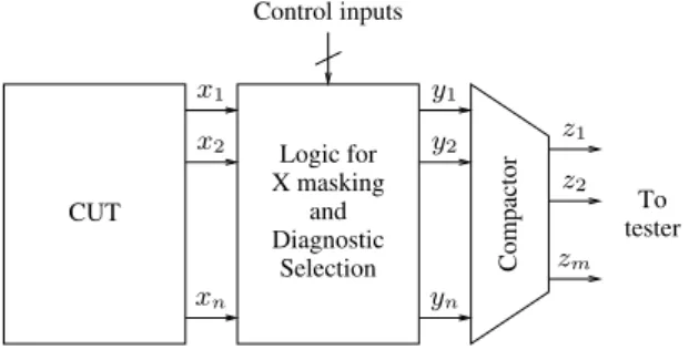
In this paper, we propose a space compactor that can be used in pass/fail mode as well as diagnostic mode. The general architecture of the circuit under test (CUT) and the compactor is presented in Figure 1. The CUT has n out- puts that can either be scan chain outputs or primary out- puts. These outputsxiare fed to a block of masking logic that can either let the signal through, i.e. yi = xi, or set yi= 0 depending on the value of the control inputs. Mask- ing is used for two reasons. First, unknown values in the test response are masked to avoid corrupting the compacted output [12, 14]. Secondly, masking is used in diagnostic mode to select the set of outputs to be observed at a given test instance by replacing the outputs that are not observed at the given step by zero values. That procedure effectively cancels the contribution of the masked output because the compactor used is linear. Finally, the test architecture con- tains a linear space compactor that transforms then signals yiintom signals zito be observed by a tester.
Logic for X masking
and Diagnostic
Selection
To tester CUT
Control inputs
Compactor
y1 y2
yn
x1 x2
xn
z1 z2
zm
Figure 1. Test architecture.
The linear compactor is based on the check matrixH of an error correcting code of distanced so that z = y.H. In other words,z is a linear combination of the n rows of H. During pass/fail test, the compaction ratio isn/m and up to d − 1 single errors in y are guaranteed to be detected. Re- garding diagnostic,t single errors in y can be diagnosed if 2t < d, assuming that unknown values are masked out by the logic inserted so that the vectorsy are fully specified. In diagnostic mode, the masking logic is set to observe onlyk outputs at a given test instance so that⌈n/k⌉ test instances are necessary for diagnostic. Reducing the number of out- puts observed improves the quality of diagnostic because it
0 0 ... 0 0 1 0 0 ... 0 0 1
0 0 ... 0 0 1 0 0 ... 0 1 0 0 0 ... 0 1 0
0 0 ... 0 1 0
1 1 ... 1 1 1 1 1 ... 1 1 1
1 1 ... 1 1 1
... ...
H0
H0
H0
k
k
k n m0
m m1
H =
Figure 2. Structure of the compactor matrix H.
is now possible to identifyt errors in the modified vector ˆy of lengthk with k < n, provided that 2t + 1 < d. How- ever, the smaller the value of k, the larger the number of test instances required and therefore the longer the test ap- plication time. For a givenk, the quality of diagnostic can nevertheless be improved by properly designing the linear compactor.
During diagnostic, the compacted output z is a linearˆ combination of the rows from a submatrix ˆH that corre- sponds to an error correcting code of distance ˆd with ˆd ≥ d. The main idea of this paper is to design the compaction ma- trixH in such a way that the submatrices ˆH have higher distance thanH in order to further improve the quality of diagnostic.
4 Compactor design
The check matrixH used in the linear space compactor is built by repeating the rows of a check matrix H0of a shorter code (ak × m0matrix) and adding extra columns as described in Figure 2. The maximum number of rows ofH depends on k and the number of extra columns m1
and is given bynmax = k.2m1−1. Therefore the maximum compaction ratio attainable is Rmax = k.2m1−1/(m0+ m1). Note that by appropriate choice of k, any arbitrarily large compaction ratio is achievable by this method. The matrix presented in Figure 2 corresponds to the special case wheren = k.2m1−1. In general, a submatrix consisting of a subset of the rows of the matrix presented in Figure 2 can be used according to the number of CUT outputsn.
Letd0be the distance of the code corresponding to the check matrixH0. During diagnostic whenk CUT outputs are observed concurrently, the compaction matrix ˆH con- sists ofH0with them1extra columns that are identical and non all zero as shown in Figure 3. Therefore the distance d is dˆ 0ifd0is even andd0+ 1 if d0 is odd. Indeed, the distance corresponds to the minimum number of rows that can add up to the zero row through binary bitwise addition. Since the lastm0bits need to add up to zero, it takes at least d0rows of ˆH to add up to the zero row of length m. Fur- thermore, ifd0is odd, then adding an odd number of rows cannot add up to the zero vector on the firstm1bits because the columns are not all zero.
...
a1a2...am1
ˆ
kH =
a1a2...am1
a1a2...am1
H0
m1 m0
Figure 3. Structure of the matrix ˆH. In pass/fail mode, the n outputs are observed together and the detection properties depend on the distance of H that is given by the following expression.
d =
! 4, if d0≥ 4
d0, if 1 < d0< 4 (1) Again, the distanced is given by the minimum number of rows ofH that add up to the zero row. Irrespective of d0, rows 1, 2,k+1 and k+2 add up to zero, which shows that d ≤ 4 in any case. Assume first that d0 ≥ 4. All the rows of H are non zero and different (the rows of H0are different sinced0> 2), thus d ≥ 3. Furthermore, if three rows add up to zero, then their subrows corresponding to the lastm0bits add up to zero. These subrows are rows ofH0that can be all different, all identical or two identical and one different. In the second and third cases, the sum cannot be zero because two cancel out and the other subrow remains (and the subrows are non zero sinced0> 1). In the first case, the three different subrows cannot add up to zero sinced0> 3. Therefore, there does not exist a set of three rows ofH that add up to zero, which shows that d > 3. Assume now thatd0= 3. Every row of H is non zero and different, which guaranteesd > 2. Furthermore, if subrows i1,i2andi3ofH0sum up to zero, then rowsi1, k+i2and 2k+i3ofH sum up to zero also. Therefore the distance of H is d = 3 = d0. Finally, assumed0= 2. Every row of H is non zero, which guarantees d > 1. Furthermore, H0
has two identical rowsi1andi2so that rowsi1andi2ofH sum up to zero. Therefore the distance ofH is d = 2 = d0. The cased0= 1 happens when H0has one or more zero rows. Ifd0 is odd, a zero row can be added toH0when
constructingH to improve the compaction ratio while ob- taining distanced0+ 1 for the augmented matrix ˆH and distanced = 3 for the pass/fail matrix H (the rows 1, k+1 and 2k+1 add up to zero, therefore the distance cannot ex- ceed three).
In pass/fail mode, up tod-1 errors out of n outputs are guaranteed to be detected, although many more combina- tions of errors are detected in practice as will be shown in Section 5. The matrixH presented here also guarantees to detect up tod0-1 errors that are located withink consecutive bits.
5 Application with Golay code
In this section, we show how the Golay code can be used to construct a space compactor following the procedure pro- posed above. The Golay code is a perfect code of distance seven, which means that it can perfectly identify up to three errors but cannot identify any group of four errors or more. We propose using the Golay code by setting H0 = HG
whereHGis the parity check matrix for the Golay code. We also propose using the augmented Golay code by adding a zero row to HG so thatH0 =
" HG
00 . . . 0
#
. We first describe the algorithms used for error detection and diag- nostic, and derive the algorithm properties for both modes. Then, we evaluate the compactors performance in terms of aliasing and misdiagnostic probabilities through simulation. 5.1 Algorithms and properties
First, we look at the simple Golay code, whose check matrixHG has 23 rows and 11 columns. The diagnostic algorithm consists of three steps and uses a dictionary that contains error signatures with the corresponding group of one, two or three error bits within the possible 23. Note that all the possible 211-1 erroneous signatures are in the dictionary since211− 1 =
$ 23 1
% +
$ 23 2
% +
$ 23 3
% . That property comes from the perfectness of the code. The diagnostic procedure is described below for a given error signatures = (sl, sr), where sland sr correspond to the m1left bits andm0right bits respectively.
Diagnostic procedure 1: for a given error signature (sl, sr),
• Find the group g of error bits corresponding to sr in the dictionary.
• Compute s′l, the left error signature for groupg.
• If s′l = sl, conclude that the group of error bits isg. Else, conclude that the errors cannot be diagnosed.
The properties of the diagnostic procedure 1 can be de- rived as follows by considering varying number of bit errors within the 23 compactor inputs. If there are three or fewer errors, they are correctly diagnosed because every such er- ror combination corresponds to a different entry in the dic- tionary. If there are four errors,slwill be zero because the same left part of the row is added an even number of times. Furthermore,srwill correspond to a groupg of three errors in the dictionary. Indeed, it cannot correspond to a group of one or two errors because the Golay code is of distance seven so that five or six rows ofHGcannot add up to zero (which is same as saying that the sum of one or two rows cannot equal the sum of four rows). However, the left hand side signature for g cannot be zero because the same left part of the row is added an odd number of times. Therefore s′l̸= sland the procedure concludes that the error cannot be diagnosed. Finally, if there are five or more errors,srmay or may not correspond to a group of error with same par- ity as the real error set. Therefore, the procedure can cause misdiagnostic by returning a set of errors that differs from the real set. It can also conclude that the errors cannot be diagnosed. We evaluate the misdiagnostic probability later in this section.
Regarding error detection in pass/fail mode, the proce- dure consists merely in comparing the signature obtained with the signature expected. As analyzed in Section 4, the matrixH has distance four and therefore it is guaranteed to detect up to three errors. Again, we will evaluate the alias- ing probability for four or more errors later in this section. Note however that careful analysis shows that five errors are also guaranteed detectable with Golay code. Indeed, by looking at the right hand side of the rows ofH correspond- ing to the errors and noting that identical right hand sides cancel in pairs, we conclude that an odd number of right hand sides remain with a maximum of five. Therefore, the right hand sides cannot add to zero because the Golay code has distance seven.
Now we consider the augmented Golay code so thatH0
has 24 rows and 11 columns. The diagnostic algorithm is given below for a given error signature s = (sl, sr). The procedure first looks for errors within the first 23 bits and then decides if bit 24 is also faulty.
Diagnostic procedure 2: for a given error signature (sl, sr),
• Find the group g of error bits corresponding to sr in the dictionary.
• Compute s′l, the left error signature for groupg.
• If s′l = sl, conclude that the group of error bits isg. Else, ifs′l̸= sland groupg contains two elements or less, conclude that both the bits of groupg and bit 24 are erroneous. Else, conclude that the errors cannot be diagnosed.
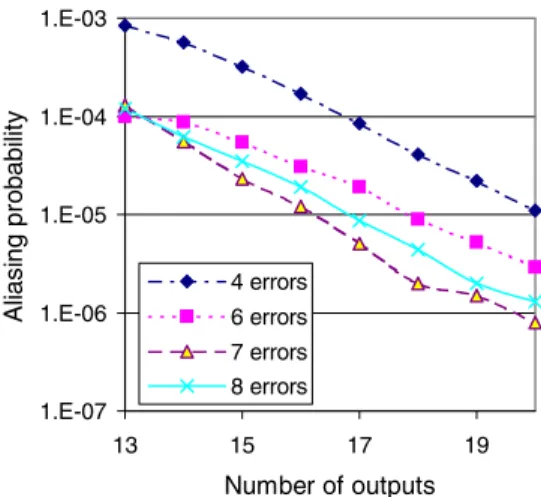
1.E-07 1.E-06 1.E-05 1.E-04 1.E-03
13 15 17 19
Number of outputs
Aliasing probability
4 errors 6 errors 7 errors 8 errors
Figure 4. Aliasing probability for 4-8 errors with simple Golay code.
Let us consider varying number of errors within the 24 compactor inputs to derive the diagnostic properties. If there are three or fewer errors within the first 23 bits, they are identified by the dictionary with correct paritys′l. If bit 24 is erroneous and two or less bits are erroneous within the remaining 23 inputs, these errors will be identified by the dictionary (note that the erroneous bit 24 does not modify the right hand side of the signaturesr). Then, the algorithm will conclude that bit 24 is also erroneous because of the parity mismatch. Therefore, three or fewer errors are guar- anteed to be correctly diagnosed. If there are four errors within the first 23 bits, then the dictionary returns a group of three errors so that the parity does not match and the al- gorithm concludes the error is not diagnosable. If bit 24 is erroneous and there are three errors within the first 23 bits, the dictionary again returns a group of three errors and the algorithm concludes the error is not diagnosable. Note that in that last case, the group of three errors returned by the dictionary was correct but the algorithm cannot conclude because it cannot differentiate that case from others where it would make mistakes. Finally, if there are five or more er- rors, the algorithm may misdiagnose the errors or conclude that the errors are undiagnosable. However, if the number of errors is odd, then the dictionary will either return a group of odd patterns that match the error parity, or a group of zero or two pattern, in which case bit 24 is declared erroneous together with the group. Therefore, misdiagnostic always occurs when the number of errors is odd and greater than five.
Regarding error detection in pass/fail mode, the proce- dure consists again in comparing the signature obtained with the signature expected. As analyzed in Section 4, the matrixH has distance three and therefore it is guaranteed to detect up to two errors. We evaluate the aliasing probability for three or more errors later in this section.
1.E-06 1.E-05 1.E-04 1.E-03
13 15 17 19
Number of outputs
Aliasing probability
3 errors 4 errors 5 errors 6 errors
Figure 5. Aliasing probability for 3-6 errors with augmented Golay code.
5.2 Performance evaluation
We now evaluate both the aliasing and the misdiagnos- tic probabilities for the compactors based on the simple and augmented Golay code. The aliasing probability is evalu- ated for a number of outputs ranging from 13 to 20, which corresponds to a number of compactor inputs ranging from 69 to 11753 for the simple Golay code and 72 to 12264 for the augmented Golay code. These numbers correspond to compaction ratios between 5 and about 600. The proba- bilities reported are averaged observations over107trials. Figure 4 shows the aliasing probability when using the sim- ple Golay code for four, six, seven and eight errors (it was shown above that sets of one, two, three or five errors are guaranteed to be detected). Note that errors of multiplicity greater than eight are not considered here as their occur- rence is usually marginal. However, we observed that their aliasing probability matches closely the results obtained for eight errors. The graph shows that the aliasing probability decreases as the number of outputs increases. The results shows the same trend as LFSR based time compactors for which the aliasing probability decreases by a factor two for every extra bit in the signature. Overall, aliasing is very un- likely, especially for compactors with many inputs. Figure 5 shows the aliasing probability when using the augmented Golay code. Results are presented for three, four, five and six errors. The graphs show again that the aliasing probabil- ity decreases as the number of outputs increases. Errors of multiplicity three and four are about ten times more likely to cause aliasing than other errors.
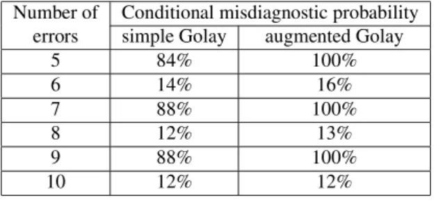
Finally, we measure the probability of misdiagnostic with the matrix ˆH based on the simple Golay and the aug- mented Golay codes. Misdiagnostic occurs when the diag- nostic procedure returns an error set different from the one that produced the erroneous signature. We showed that such event can happen when five or more errors are present at the
Number of Conditional misdiagnostic probability errors simple Golay augmented Golay
5 84% 100%
6 14% 16%
7 88% 100%
8 12% 13%
9 88% 100%
10 12% 12%
Table 1. Misdiagnotic probability
compactor inputs. The results presented in Table 1 show that misdiagnostic is very frequent for odd number of er- rors and less frequent for even number of errors. It is due to the fact that the dictionary contains entries that correspond mainly to three errors (1771 entries correspond to combi- nations of three errors, 253 for two errors and 23 for single errors). When using the augmented Golay code, errors of multiplicity greater than five and odd are always misdiag- nosed because the procedure declares the input number 24 erroneous whenever the erroneous signature corresponds to an error of multiplicity two in the dictionary. Note that the diagnostic procedure is still very efficient because it guaran- tees correct diagnostic of errors of multiplicity three or less and no misdiagnostic for errors of multiplicity four, which are very predominant events in general. Assuming that er- rors are uniformly distributed, the misdiagnostic probability is 3.7 10−3if the error probability is 5% and it remains be- low 2.4 10−6if the error probability is below 1%.
6 Conclusion
This paper proposes a linear space compaction scheme that can be used during pass/fail mode to detect the pres- ence of errors in the test response and also during diagnos- tic mode to identify the location of errors within the test response while observing merely the compacted outputs. Enhanced diagnostic capabilities are achieved by reducing the compaction ratio during diagnostic mode in such a way that the distance of check matrix used in the compactor in- creases.
The method can be used with various basic blocks to achieve different diagnostic performance and compaction ratio. We presented a detailed analysis of the compactor ob- tained using the Golay code and its augmented version. Any combination of three errors out of 23 inputs can be identi- fied from only 12 outputs, thus preserving a compaction ra- tio of almost two during diagnostic. The use of other codes such as BCH codes of arbitrary distance remains to be stud- ied. Also, the impact of X values on diagnostic performance should be evaluated and the design of compactors for diag- nostic in the presence of X values should be considered.
Acknowledgments
This work was supported in part by 21st Century COE Program and in part by Japan Society for the Promotion of Science (JSPS) under Grants-in-Aid for Scientific Research B(2)(No. 15300018) and the grant of JSPS Research Fel- lowship (No. L04509).
References
[1] I. Bayraktaroglu and A. Orailoglu. Deterministic partition- ing techniques for fault diagnosis in scan-based bist. In Proc. ITC, pages 273–282, 2000.
[2] I. Bayraktaroglu and A. Orailoglu. Improved fault diagnosis in scan-based bist via superposition. In Proc. DAC, pages 55–58, 2000.
[3] I. Bayraktaroglu and A. Orailoglu. Diagnosis for scan-based bist: Reaching deep into the signatures. In Proc. DATE, pages 102–109, 2001.
[4] J. Chan and B. Womack. A study of faulty signature for diagnostics. In Proc. ISCAS, pages 2701–2704, 1990. [5] T. Clouqueur, O. Ercevik, K. Saluja, and H. Takahashi. Effi-
cient signature-based fault diagnosis using variable size win- dows. In Proc. VLSI Design, pages 391–396, 2001. [6] J. Ghosh-Dastidar, D. Das, and N. Touba. Fault diagnosis in
scan-based bist using both time and space information. In Proc. ITC, pages 95–102, 1999.
[7] J. Ghosh-Dastidar and N. Touba. A rapid and sclable diag- nosis scheme for bist environments with a large number of scan chains. In Proc. VTS, pages 79–85, 2000.
[8] A. Leininger, M. Goessel, and P. Muhmenthaler. Diagnosis of scan-chains by use of a configurable signature register and error-correcting codes. In Proc. DATE, volume 2, pages 1302 – 1307, 2004.
[9] C. Liu and K. Chakrabarty. A partition-based approach for identifying failing scan cells in scan-bist with applications to system-on-chip fault diagnosis. In Proc. DATE, pages 230– 235, 2003.
[10] W. McAnney and J. Savir. There is information in faulty signatures. In Proc. ITC, pages 630–636, 1987.
[11] G. Mrugalski, A. Pogiel, J. Rajski, J. Tyszer, and C. Wang. Fault diagnosis in designs with convolutional compactors. In Proc. ITC, pages 498 – 507, 2004.
[12] M. Naruse, I. Pomeranz, S. M. Reddy, and S. Kundu. On- chip compression of output responses with unknown values using lfsr reseeding. In Proc. ITC, pages 1060–1068, 2003. [13] J. H. Patel, S. S. Lumetta, and S. M. Reddy. Application
of saluja-karpovsky compactors to test responses with many unknowns. In Proc. VTS, pages 107–112, 2003.
[14] I. Pomeranz, S. Kundu, and S. M. Reddy. On output re- sponse compression in the presence of unknown output val- ues. In Proc. DAC, pages 255–258, 2002.
[15] J. Rajski and J. Tyszer. On the diagnostic properties of linear feedback shift register. IEEE Trans. on CAD, 10:1316–1322, oct 1991.
[16] J. Rajski and J. Tyszer. Diagnosis of scan cells in bist envi- ronment. IEEE Trans. on Computers, 48:724–731, jul 1999. [17] K. K. Saluja and M. Karpovsky. Testing computer hardware through data compression in space and time. In Proc. ITC, pages 83–88, 1983.
[18] J. Savir. Salvaging test windows in bist diagnostics. In Proc. VTS, pages 416–425, 1997.
[19] J. Savir and W. McAnney. Identification of failing tests with cycling registers. In Proc. ITC, pages 322–328, 1988. [20] C. Stroud and T. Damarla. Improving the efficiency of error
identification via signature analysis. In Proc. VTS, pages 244–249, 1995.
[21] P. Wohl, J. Waicukauski, S. Patel, and G. Maston. Effective diagnostics through interval unloads in a bist environment. In Proc. DAC, pages 249–254, 2002.
[22] Y. Wu and M. Adham. Scan-based bist fault diagnosis. IEEE Trans. on CAD, 18:203–211, feb 1999.