Fault Set Partition for Efficient Width Compression
1Emil Gizdarski* and Hideo Fujiwara**
* Synopsys Inc., Mountain View, CA 94043
** Nara Institute of Science and Technology, Ikoma, Nara 630-0101, Japan E-mail: [email protected], [email protected]
1 This work was partly supported by JSPS under grant P99747
Abstract
In this paper, we present a technique for reducing the test length of counter-based pseudo-exhaustive built-in self-testing (BIST) using width compression method and a divide-and-conquer strategy. More formally, the target faults are divided into K groups such that a binary counter can generate a test set for each group. By selecting the size of the binary counter, this technique allows a trade-off between test application time and area overhead. The experimental results for the ISCAS’85 and ISCAS’89 benchmark circuits demonstrate the efficiency of the proposed technique. In all cases, this low-overhead BIST technique achieves complete fault coverage of the stuck-at faults in reasonable test application time.
1. Introduction
Logic BIST is gaining acceptance in the VLSI industry because it eliminates the need of expensive external test equipment as well as provides at-speed and in-system testing capabilities [1,5]. In a core-based strategy, the circuit is partitioned into a number of circuits under test (CUT). Each CUT has an associated test pattern generator (TPG) and output response analyzer - a multiple-input signature register (MISR). The efficiency of a BIST technique strongly depends on the abilities to design low- overhead TPGs that achieves very high fault coverage with acceptable test lengths. Different design & test techniques have addressed this problem, e.g., pseudo-exhaustive (verification) testing [2,22], pseudo-random testing [4,5,10,20,25,26,27], and deterministic test set embedding [14,19,28]. Recently, the width compression method [8,9,12] has been introduced to further reduce the test length of the pseudo-exhaustive testing. In general, the width compression method is based on finding compatibility relations between the inputs of the CUT. Unlike pseudo-exhaustive testing [2,22], two inputs are considered compatible if they can be connected to the same output of the TPG without any loss of fault coverage. In general, the target fault set may include different type of faults, however, for simplicity, we consider here only stuck-at faults.
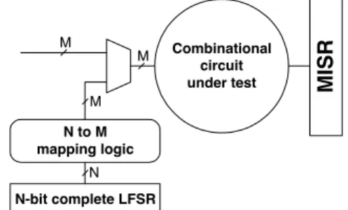
Figure 1 illustrates a test-per-clock scheme of the counter-based exhaustive BIST. Accordingly, we assume a TPG implemented using an N-bit binary counter or complete LFSR, called a de Bruijn counter [5]. This scheme also includes mapping logic connected via multiplexers (MUXs) to the inputs of an M-input combinational CUT where M>>N. In this case, the width
compression method is used to minimize the size of the counter by finding as many compatibility relations as possible between the inputs of the CUT. Four compatibility relations have been introduced recently in the literature: direct and inverse compatibility [9], decoder compatibility [8] and combinational compatibility [12]. As a result, the mapping logic in [9] includes only direct connections and inverters, while the mapping logic in [8] and [12] includes also binary decoders and 2-input gates, respectively.
The advantage of the counter-based pseudo-exhaustive testing is that it achieves complete fault coverage of the target faults with a low-area overhead. Despite recent improvements [12], counter-based BIST techniques still require relatively long test length (up to 223 and 226 for the ISCAS’85[6] and ISCAS’89[7] benchmark circuits, see column 6 in Table 1) which limits their application to the test-per-clock scheme. In this paper, we address this problem and propose a new technique based on the divide- and-conquer strategy to further reduce the test length of the counter-based BIST. More formally, we divide the target faults into K groups such that a binary counter can generate a test set for each group.
The rest of this paper is organized as follows. In section 2, the compatibility relations previously introduced in the literature are summarized as well as a new compatibility relation allowing further reduction of the test length of the counter-based BIST is presented. In Section 3, the synthesis procedure is shown. In Section 4, the experimental results are given and Section 5 concludes the paper.
2. New compatibility relation
In this section, we first summarize the compatibility relations previously introduced in the literature. Next, we
Figure 1: A test-per-clock scheme of the counter- based BIST
N-bit complete LFSR N to M mapping logic
N M M
M
MISR
Combinational circuit under test
IEEE the 11th Asian Test Symposium (ATS'02), pp. 194-199, Nov. 2002.
present a new compatibility relation for reducing the test length of the counter-based exhaustive testing.
Two inputs of a combinational circuit are said to be directly compatible if they can be shorted together without introducing any redundant stuck-at fault in the circuit. Similarly, two inputs of a circuit are said to be inversely compatible if they can be shorted together via inverter without introducing any redundant stuck-at fault in the circuit [9].
A set of inputs of a circuit is said to form a compatibility class if all inputs are directly or inversely compatible to one another, i.e., shortening together by wire or via inverters to one output of TPG does not introduce any redundant fault in the CUT. As the same (or opposite) logic value is applied to all inputs in a compatibility class during testing, the size of the binary counter used for the counter-based exhaustive testing is equal to the number of compatibility classes, i.e., the test length is 2N where N is the number of compatibility classes.
Two or more inputs of a circuit are said to be decoder- compatible (D-compatible) if all detectable stuck-at faults in the circuit can be tested by a test set in which no test vector requires more than one of these inputs to be at value one [8]. This compatibility relation can be used to further reduce the size of the binary counter since the values of D- compatible inputs x1,x2,..,xk can be generated by a counter connected to the inputs x1,x2,..,xk via a decoder.
In [12], a compatibility relation called combinational compatibility (Ck-compatibility) has been introduced to further reduce the test length of the counter-based exhaustive testing. We use this definition because it covers all previous definitions presented in the literature.
Definition of Ck-compatibility relation [12]: Inputs x1,x2,.., xk of a circuit are said to be Ck-compatible with input xk+1 if a combinational circuit z=f(x1,x2,..,xk) exists whose output z can be connected to input xk+1 without introducing any redundant fault in the circuit.
For example, the direct and inverse compatibility relations introduced in [9] can be viewed as C1- compatibility relation. Also, the D-compatibility relation introduced in [8] is a special case of Ck-compatibility where the combinational circuit is a decoder. The disadvantage of the Ck-compatibility relation is its extremely high time-complexity when K>2 because, in the worst case, all combinations of (K+1) compatibility classes have to be checked with all possible k-input combinational functions z=f(x1,x2,..,xk). For example, the number of these functions when k=2 and 3 is 10 and 218, respectively. The next compatibility relation can be used to further reduce the test length of the counter-based pseudo-exhaustive testing and keep the time-complexity for width compression at a reasonable level.
New compatibility relation: Let {c1,c2,..,cN) be the set of compatibility classes for a given circuit. Let βi define a partition of the set of compatibility classes into S blocks {bi1,bi2,…,biS} each one consisting of one or more compatibility classes. Let λ(βi) be a set of the redundant faults introduced by partition βi. Then partitions {β1,β2,..,βk} defines a composite Pk-compatibility relation
iff the set of untested faults, ∆λk=λ(β1)∩λ(β2) ∩…∩ λ(βk)=∅, is empty.
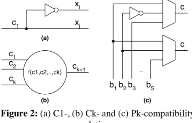
Figure 2 depicts the compatibility relations. Accordingly, the C1-compatibility relation allows two or more inputs of the CUT to be connected to the same output of the TPG if this does not introduce any redundant fault in the CUT, Figure 2(a). In this case, the mapping logic can contain only wires and inverters. Next, the Ck- compatibility relation allows a further reduction of the compatibility classes if a compatibility class ck+1 can be represented as a logic function of others k compatibility classes c1,c2,..,ck without introducing any redundant fault in the CUT. This is shown in Figure 2(b). In this case, the mapping logic can contain wires, inverters as well as any type of k-input logic gates: AND, OR and XOR. Finally, the Pk-compatibility allows any Ck-compatibility class to belong to different blocks b1,b2,..,bS for each partitions β1,β2,..,βk. In this way, two compatibility classes, ci and cj, can be independent, directly or inversely compatible in different partitions, Figure 2(c).
Clearly, the test length for the counter-based exhaustive testing using the proposed Pk-compatibility relation is equal to 2S1 + 2S2 + ... + 2Sk where Si is the number of blocks for partition βi. Also, if we accept that the number of blocks of all partitions is equal to S, then the test length of the counter-based exhaustive testing using Pk- compatibility relation becomes K2S.
3. Synthesis procedure
In this section, we present a design for test (DFT) synthesis procedure for a test-per-scan scheme using Pk- compatibility relation. First, we present the target BIST scheme. Next, we describe the procedure for deriving C1- compatibility relation. Finally, we describe the procedure for reducing the test length of exhaustive testing using Pk- compatibility relation.
3.1. Test-per-scan scheme
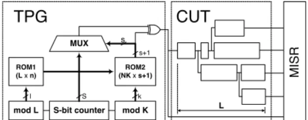
Figure 3 presents the target test-per-scan scheme of the counter-based exhaustive BIST. Accordingly, we assume a full-scan approach, i.e., in test mode the CUT is transformed into a combinational circuit and all primary inputs and internal registers are included into a scan chain. Also, the scan flip-flops are divided into two or more scan chains each one having at most L flip-flops such that all
f(c1,c2,..,ck)
c1 c2 ck
ck+1
. . .
xi xj c1
...
ci
cj
b1b2b3 bS
(a)
(b) (c)
Figure 2: (a) C1-, (b) Ck- and (c) Pk-compatibility relations
flip-flops in position i of all scan chains are directly compatible for ∀i∈{1,..,L}. This precondition can be achieved using pseudo-exhaustive technique [2,22], i.e., initially, two inputs are considered as compatible if they do not belong to a cone (primary output). The proposed BIST architecture is very similar to the Illinois scan architecture presented in [13]. The differences are that the proposed scheme has only one test mode corresponding to the broadcast test mode of Illinois scan, and the pseudo- exhaustive technique [2,22] is used during DFT synthesis, i.e., the scan chain synthesis is based on dependency matrix [22] and does not involved ATPG (i.e. width compression).
The TPG consists of two ROM’s, a complex binary counter and multiplexer. The first section of the complex counter is a counter modulo L which, together with ROM1, determines the compatibility class for each flip- flop in the scan chains. More formally, ROM1 contains information for the compatibility classes of all scan flip- flops. Because all flip-flops in position i of all scan chains belong to one compatibility class, let say cj, ROM1 in address (L-i) should contain an unique n-bit integer corresponding to compatibility class cj where n=log2N. Similarly, the third section of the complex counter is a counter by modulo K that together with ROM2 determines the block of each compatibility class for each partition, i.e., the bit of the S-bit counter that has to be shifted during the current shift-in cycle. For example, if compatibility class ci
in partition βj belongs to block bjm, where i∈{1,..,N}, j∈{1,..,K} and m∈{1,..,S}, then ROM2 in address N(j- 1)+(i-1) should contain an unique s-bit integer corresponding to the block bjm where s=log2S. In fact, ROM2 has (s+1)-bit word and the most significant bit determines the type of compatibility relation – directly or inversely – between the compatibility classes within one block. For example, if compatibility classes cx and cy in partition βj belong to one block and are directly or inversely compatible, then the most significant bits in addresses N(j-1)+x-1and N(j-1)+y-1 should have equal or different values, respectively.
An important aspect of BIST is to achieve a self-testing of TPG. In this case, BIST is able to detect not only the target faults in the CUT but also any single stuck-at fault in the TPG. Otherwise, many detectable faults in the CUT may remain untested because of a fault in the TPG. This goal is easily achieved in the proposed BIST scheme by
connecting the only output of the TPG to the MISR as shown in Figure 3.
Next, let us consider how to facilitate satisfying the precondition of the proposed BIST scheme that all flip- flops in the position i for ∀i=(1,..,L) are directly compatible. Clearly, if the CUT has only one scan chain, then this precondition is always satisfied. Therefore, by choosing a proper value for parameter L, a trade of between the area overhead in the TPG and scan chains as well as test application time can be achieved. For example, by choosing a high value for parameter L, we increase the degree of freedom for ordering and reordering the scan chains but also increase the size of ROM1 and test application time. To increase the degree of freedom for DFT synthesis, we propose a tree-structure of the scan chains depicted in Figure 3. In this way, if the value of parameter L is properly selected, then this structure of scan chains allows satisfying the precondition of the proposed test-per-scan scheme by slight or even without reordering of the scan chains.
3.2. Deriving compatibility classes
The procedure for deriving compatibility classes is based on a greedy strategy. More formally, the first input is assigned to the first compatibility class. Next, if the current input is compatible to all inputs in an existing compatibility class, then this input is added to that compatibility class, otherwise this input is assigned to a new compatibility class.
Deriving the compatibility classes requires checking the compatibility of a set of inputs. The synthesis procedure uses techniques similar to those presented in [8,9,12]. These techniques are based on dependency matrix [22], incompatibility filters [9] and fault set reduction [12]. After quick identification of a large number of compatible inputs using dependency matrix, the synthesis procedure tries to reduce the number of compatibility classes using test generation. This technique checks whether shorting two inputs together introduces any redundant fault in the CUT. The search space in this phase can be considerably reduced using incompatibility filters. More formally, the synthesis procedure calculates the incompatibility filters using both structural information and necessary input assignments of each fault in the target set. Accordingly, two inputs of a circuit are incompatible if they are inputs of one logic gate [9]. Also, two inputs of a circuit are inversely (directly) incompatible, if a necessary input assignment to detect a fault requires both inputs to be at the same (different) values [12].
This phase is speeded up by a dynamic update of test set during width compression. For example, when checking the compatibility of two inputs, xa and xb, the synthesis procedure identifies test patterns that have incompatible values for these inputs. Next, these test patterns are temporarily removed from test set and all faults detected by them become potentially redundant (or untested). These faults form the fault list to be checked by ATPG. After shortening inputs xa and xb together (via wire or inverter), if all faults in the fault list are proven to be detectable then these inputs are compatible and test set is Figure 3: A test-per-scan scheme of the counter-
based exhaustive BIST
S k
MUX s
ROM2 (NK x s+1) ROM1
(L x n)
S-bit counter mod K mod L
l
s+1
TPG CUT
...
L
MISR
undated, otherwise these inputs are incompatible and test set is restored.
3.3. Fault set partition
In general, two approaches for width compression based on test generation [9,12] and computed minimal test sets [8] exist. The divide-and-conquer strategy for width compression will result in fault set and test set partition, respectively.
From a practical point of view, two different tasks for fault test partition are possible: (1) minimize K the number of partitions when the size S of the counter is fixed and (2) minimize test length when K=2. Both tasks assume a similar approach, so we present here the synthesis procedure for the first case.
Procedure 1: The input data are the CUT, the compatibility classes, parameter S, and the target fault set,
∆λ(β0), i.e., including all detectable single stuck-at faults. The output data are partitions β1,β2,..,βk of the compatibility classes into S blocks such as the set ∆λ(βk), calculated as an intersection of the redundant faults introduced by partitions β1,β2,..,βk is empty.
K=0; while ∆λ(βk)≠∅ do the following:
1) K=K+1; derive partition βk using a greedy strategy to minimize ∆λ(βk). Initially, the number of blocks of partition βk is equal to N – the number of compatibility classes. Next, if two blocks are merged then the number of blocks in partition βk decreases by 1. This step continues until the number of blocks in partition βk becomes equal to S.
2) Optimize partition βk by checking whether each compatibility class can be included to another block so that
∆λ(βk) is minimized.
Procedure 1 is based on a dynamic calculation and minimization of ∆λ(βk) - the number of redundant faults introduced by merging blocks of partition βk. This analysis is speeded up by filtering the pairs of blocks that merged together introduce too many redundant faults. Also, Procedure 1 utilizes the following assumption:
Assumption 1: Let ∆λ(β) be estimated by calculating a square matrix λ such that the entry (x,y) is equal to the number of redundant faults introduced by merging directly (or inversely) blocks bx and by where x<y (or x>y), respectively. The number of redundant faults introduced by merging two or more pairs of blocks can be estimated as the sum of corresponding entries in matrix λ if each new block is formed by merging at most two blocks, i.e., no new block is formed by merging together three or more blocks.
Example 1: Figure 4 shows matrix λ of partition β where entry (4,3) determines that if blocks b3 and b4 are inversely merged together, then the number of introduced redundant faults is 17. Now let us suppose that we would like to find two pairs of blocks that merged together introduce a minimum number of redundant faults. According to Assumption 1, this goal can be achieved if blocks b1 and b6 are inversely merged and blocks b2 and b7 are directly merged, i.e., the selected pairs are (6,1) and
(2,7). In this case, the number of blocks is 6 and the number of redundant faults introduced by this merge is estimated to be 4. Now let us suppose that we would like to find three pairs of blocks. According to Assumption 1, to minimize the number of introduced redundant faults, the selected pairs are (2,7), (3,6) and (1,5). In this case, the number of blocks is 5 and the number of the redundant faults introduced by this merge is estimated to be 9.
In fact, Assumption 1 is very useful when the number of blocks is bigger than 30. In this case, just 2-3 iterations are necessary to reduce by 50 percents the number of blocks.
4. Experimental results
The presented synthesis procedure was implemented using ATPG system SPIRIT[11] and ran on a 1GHz Pentium-III PC. The experimental results for the ISCAS’85[6] benchmark circuits and a full-scan version of the ISCAS’89[7] benchmark circuits are presented in Tables 1 and 2.
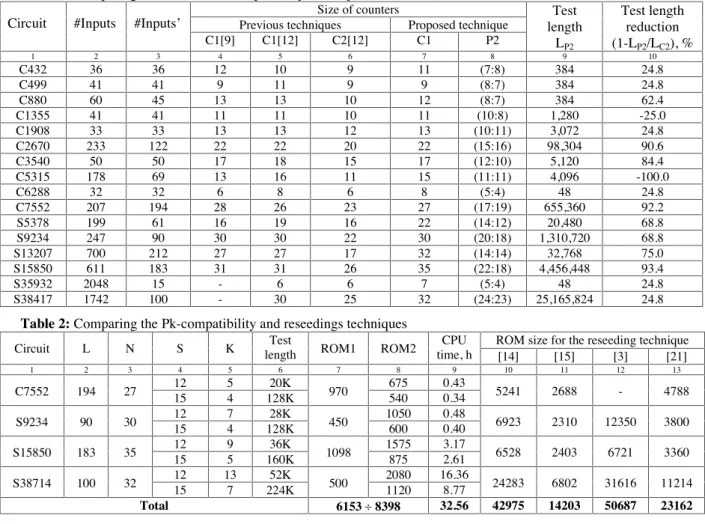
Table 1 presents a comparison of the P2- and C2- compatibility relation – chosen here as an alternative technique for width compression. Columns 2-6 give the number of inputs before and after width compression based on pseudo-exhaustive testing [2,22], C1-compatibility relation [9] and C2-compatibility relation [12]. Columns 7-9 show the experimental result of the proposed P2- compatibility technique. These results include the number of compatibility classes obtained by the first step of the synthesis procedure, the numbers of block of partitions β1 and β2, respectively, S1 and S2 as well as the test length of the counter-based exhaustive testing calculated by the formula 2S1 + 2S2. Column 10 shows the test length reduction of the P2-compatibility techniques calculated by the formula (1-LP2/LC2) in percents where LC2 and LP2 are the test lengths of the C2- and P2-compatibility techniques. These results demonstrate the effectiveness of the proposed P2-compatibility technique in respect to the C2- compatibility technique. In all critical cases, i.e., the cases where the test length of the C1-compatibility technique is bigger than 220, the test length reduction was between 24.8 and 93.4 percents. In fact, the proposed and alternative techniques for width compression do not contradict each other and they can be applied together to further reduce the test length of the counter-based exhaustive testing.
Figure 4: A square matrix λ where S=8
2 3 4 5 6 7 8
1 1 2 3 4 5 6 7 8
- 12
3 12 6 7 5
18 - 17 32 21 19 8
7 23 - 12
4 12 17
12 6 23 - 14 14 13
5 3 12 12 - 13
5 2 13 8 6 22 - 9-
12 9 11 9 17 13 - 12
6 8 5 2 13 8
2 8 12 4 8 18 32 -
Table 2 presents experimental results for the Pk- compatibility technique when the number of blocks of each partition were fixed to 12 and 15, i.e., S=12 and S=15. Columns 2-9 show the maximum length of scan chains, the number of compatibility classes, blocks and partitions obtained after the first and second steps of the synthesis procedure, the test length of counter-based exhaustive testing, the ROM sizes and CPU time in hours only for the second step of the synthesis procedure. Columns 12-15 give ROM sizes of the best-published results for the reseeding technique - chosen here as an alternative technique. The size of the ROM for the proposed BIST technique was calculated by the following formula: nL + (s+1)KN where n=log2N and s=log2S. Obviously, the proposed BIST technique achieved higher compression of test data than the reseeding technique. In fact, some of these results for the reseeding technique were achieved using also Pseudo Random Test Generation (PRTG) [14,15,21] as well as width compression method [15]. For example, if we use the structure of scan chains proposed in [15], then ROM1 in Figure 3 will become redundant. Also, these results show that the size of ROM’s for the proposed BIST technique slightly depends on the size of the circuits. For the typical cores (10K-100K gates) [18], we may expect L≤512, N≤64, K≤16 and S≤16, i.e., the test length and the size of ROM’s will be less than 1M and 8K, respectively.
Now, let us compare this technique with other BIST techniques that achieve complete fault coverage. The most promising scan-based techniques able to achieve this goal by reasonable test application time are based on reseeding [3,14,15,21] and bit-flipping [18,28]. In this analysis, we exclude the test point insertion technique [24] because this technique does not guarantee complete fault coverage [16]. The advantages of the proposed BIST technique are: 1) low area overhead (estimated here by the size of the ROM) that depends slightly on the size of the CUT; 2) higher test length reduction than the previously published counter- based pseudo-exhaustive techniques; 3) ability to achieve a trade-off between area overhead and test application time when complete fault coverage of the single stuck-at faults in both the CUT and TPG is ensured.
The disadvantage of the proposed BIST technique is the time complexity of the synthesis procedure involving many runs of ATPG for the whole or reduced fault set. Alternatively, PRTG techniques and dynamic-scan chain approaches [13,17,23] can be used. For example, some recently published results demonstrated the ability of the weighted random techniques [26,27] to achieve very high fault coverage. Therefore the target fault set can be considerably reduced using PRTG. As a result, the synthesis procedure could be speeded up significantly.
5. Conclusions
We presented a new technique for reducing the test length of the counter-based BIST using the width compression method and the divide-and-conquer strategy. The experimental results for the ISCAS’85 and ISCAS’89 benchmark circuits demonstrated the effectiveness of the
proposed BIST technique. When K=2 (fault set partition in two groups), much shorter test length was achieved than the previously published counter-based pseudo-exhaustive BIST techniques in all critical cases. A further reduction of the test length was achieved by increasing parameter K (the number of groups for fault set partition). As a result, the proposed BIST technique achieved the highest compression of test data of all previously published deterministic BIST techniques. Also, the size of the test data depends slightly on the size of the CUT. These results were achieved using a new test-per-scan BIST architecture where test data were represented as Pk-compatibility relations.
References:
[1] M. Abramovici, M. Breuer and A. Friedman,
“Digital Systems Testing and Testable Design”, IEEE Computer Science Press, 1990.
[2] Z. Barzilai, J. Savir, G. Markowsky and M. G. Smith, “VLSI Self-Testing Based on Syndrome Techniques,” Proc. IEEE ITC, 1981, pp.102-109.
[3] K. Chakrabarty and S. Swaminathan, “Built-In Self- Testing of High-Performance Circuits using Twisted-Ring Counters,” Proc. IEEE ISCAS, 2000, pp.72-76.
[4] P. H. Bardell, W. McAnney, “Self-Testing of Multichip Logic Modules, Proc. IEEE ITC, 1982, pp.200- 204.
[5] P. H. Bardell, W. McAnney and J. Savir, “Built-In Test for VLSI: Pseudorandom Techniques,” John Wiley & Sons, NY, 1987.
[6] F. Brglez and H. Fujiwara, "A Neutral Netlist of 10 Combinational Benchmark Circuits and a Target Translator in Fortran," Proc. IEEE ISCAS 1985, pp. 663- 698.
[7] F. Brglez, D. Bryan and K. Kozminski,
"Combinational Profiles of Sequential Benchmark Circuits," Proc. IEEE ISCAS 1989, pp.1929-1934.
[8] K. Chakrabarty, B. Murray, J. Liu and M. Zhu,
“Test Width Compression for Built-in Self Testing,” Proc. IEEE ITC, 1997, pp.328-337.
[9] C. Chen and S. K. Gupta, “A Methodology to Design Efficient BIST Test Pattern Generators,” Proc. IEEE ITC, 1995, pp.814-823.
[10] F. Corno, M. Reorda, G. Squillero and M. Violante, “CA-CSTP: A New BIST Architecture for Sequential Circuits”, Proc. IEEE ETW, 2000, pp.167-171.
[11] E. Gizdarski and H. Fujiwara, ”SPIRIT: A Highly Robust Combinational Test Generation Algorithm,” Proc. IEEE VTS, 2000, pp.346-351.
[12] I. Hamzaoglu and J. H. Patel, “Reducing Test Application Time for Built-in Self-Test Test Pattern Generators,” Proc. IEEE VTS, 2000, pp.369-375.
[13] I. Hamzaoglu and J. H. Patel, “Reducing Test Application Time for Full Scan Embedded Cores,” Proc. IEEE FTCS, 1999, pp.260-267.
[14] S. Hellebrand, J. Rajski, S. Tarnick, S. Venkataraman and B. Courtois, “Built-in Test for Circuits with Scan Based on Reseeding of Multiple-Polynomial
Linear Feedback Shift Registers,” IEEE Trans. on Computers, vol.C-44, No.2, Feb. 1995, pp.223-233.
[15] S. Hellebrand, H. Liang and H. Wunderlich, “A Mixed Mode BIST Scheme Based on Reseeding of Folding Counters,” Proc. IEEE ITC, 2000, pp.778-784.
[16] G. Hetherington, T. Fryars, N. Tamarapalli, M.Kassab, A.Hassan and J.Rajski, “Logic BIST for Large Industrial Designs: Real Issues and Case Studies”, Proc. IEEE ITC, 1999, pp.358-367.
[17] R. Kapur, D. Martin and T. Williams, “Dynamic Scan Chains and Test Generation Methodologies Therefore, “ December 1999, SNSY-A-1999-022.
[18] G. Kiefer, H. Vranken, E. Marinissen and H. Wunderlich, “Application of Deterministic Logic BIST on Industrial Circuits,” Proc. IEEE ITC, 2000, pp.105-114.
[19] B. Koenemann, “LFSR-Cored Test Patterns for Scan Designs,” Proc. IEEE European Test Conference, 1991, pp.237-242.
[20] A. Krasniewski and S. Pilarski, “Circular Self-Test Path: A Low-cost BIST Technique for VLSI Circuits,” IEEE Trans. on CAD, vol.8, No.1, Jan. 1989, pp.46-55.
[21] H. Liang, H. Wunderlich and S. Hellebrand,
“Two-Dimensional Test Data Commpression for Scan- Based Deterministic BIST,” IEEE ITC, 2001, pp 894-902.
[22] E. J. McCluskey, “Verification Testing – A Pseudoexhaustive Test Technique,” IEEE Trans. on Computers, vol.C-33, No.6, June 1984, pp.541-546.
[23] N. Sitchinava, S. Samaranayake, R. Kapur, M. Amin, T. Williams, “DFT – ATE Solution to Lower the Cost of Test, IEEE Workshop on Test Resource Partitioning, Nov. 2001, Atlantic Sity.
[24] N. Tamarapalli and J. Rajski, “Constructive Multi- Phase Test Point Insertion for Scan-Based BIST,” Proc. IEEE ITC, 1996, pp.649-658.
[25] N. A. Touba and E. J. McCluskey, “Synthesis of Mapping Logic for Generating Transformed Pseudo- Random Patterns for BIST,” Proc. IEEE ITC, 1995, pp.674-682.
[26] K. Tsai, J. Rajski and M.Marek-Sadowska, “Star Test: The Theory and Its Application”, IEEE Trans. on CAD, vol.19, No.9, Sept.2000, pp.1052-1063.
[27] S. Wang, “Low Hardware Overhead Scan Based 3-Weight Weighted Random BIST,” Proc. IEEE ITC, 2001, pp.868-877.
[28] H. Wunderlich and G. Kiefer, “Bit-Flipping BIST,” Proc. IEEE ICCAD, 1996, pp.337-343.
Table 1: Comparing the P2- and C2-compatibility techniques Size of counters
Previous techniques Proposed technique Circuit #Inputs #Inputs’
C1[9] C1[12] C2[12] C1 P2
Test length
LP2
Test length reduction (1-LP2/LC2), %
1 2 3 4 5 6 7 8 9 10
C432 36 36 12 10 9 11 (7:8) 384 24.8
C499 41 41 9 11 9 9 (8:7) 384 24.8
C880 60 45 13 13 10 12 (8:7) 384 62.4
C1355 41 41 11 11 10 11 (10:8) 1,280 -25.0
C1908 33 33 13 13 12 13 (10:11) 3,072 24.8
C2670 233 122 22 22 20 22 (15:16) 98,304 90.6
C3540 50 50 17 18 15 17 (12:10) 5,120 84.4
C5315 178 69 13 16 11 15 (11:11) 4,096 -100.0
C6288 32 32 6 8 6 8 (5:4) 48 24.8
C7552 207 194 28 26 23 27 (17:19) 655,360 92.2
S5378 199 61 16 19 16 22 (14:12) 20,480 68.8
S9234 247 90 30 30 22 30 (20:18) 1,310,720 68.8
S13207 700 212 27 27 17 32 (14:14) 32,768 75.0
S15850 611 183 31 31 26 35 (22:18) 4,456,448 93.4
S35932 2048 15 - 6 6 7 (5:4) 48 24.8
S38417 1742 100 - 30 25 32 (24:23) 25,165,824 24.8
Table 2: Comparing the Pk-compatibility and reseedings techniques
ROM size for the reseeding technique Circuit L N S K length Test ROM1 ROM2 time, h CPU
[14] [15] [3] [21]
1 2 3 4 5 6 7 8 9 10 11 12 13
12 5 20K 675 0.43
C7552 194 27
15 4 128K 970 540 0.34 5241 2688 - 4788
12 7 28K 1050 0.48
S9234 90 30
15 4 128K 450 600 0.40 6923 2310 12350 3800
12 9 36K 1575 3.17
S15850 183 35
15 5 160K 1098 875 2.61 6528 2403 6721 3360
12 13 52K 2080 16.36
S38714 100 32
15 7 224K 500 1120 8.77 24283 6802 31616 11214
Total 6153 ! 8398 32.56 42975 14203 50687 23162