Using Domain Partitioning in Wrapper Design for IP Cores Under Power
Constraints
Thomas Edison Yu
†, Tomokazu Yoneda
†, Danella Zhao
‡and Hideo Fujiwara
††
Graduate School of Information Science, Nara Institute of Science and Technology
Kansai Science City, 630–0192, Japan
‡
The Center For Advanced Computer Studies, University of Louisiana at Lafayette
Lafayette, LA, 70504
† E–mail:¶tomasu-y, yoneda, fujiwara}@is.naist.jp, Tel.:+81-743-72-5222, Fax:+81-743-72-5229
‡ E–mail:¶dzhao}@cacs.louisiana.edu, Tel:(337) 482-6875, Fax:(337) 482-5791
Abstract
This paper presents a novel design method for power-aware test wrappers targeting embedded cores with multiple clock domains. We show that effective partitioning of clock domains combined with bandwidth conversion and gated-clocks would yield shorter test times due to greater flexibility when determining optimal test schedules especially under tight power constraints.
Keywords:
multi-clock domain, wrapper design, SoC, embedded core test, test scheduling
1 Introduction
SoCs (System-on-Chip) are widely used in networking, telecommunications, and digital signal processing which increases the demand for highly reliable, defect-free chips. Because of the increased circuit complexity of SoCs, test engineers are faced with larger amounts of test data and test access design problems. Moreover, modern IP cores operate at various frequencies internally which have advantages such as reduced power and silicon area. These multi-clock domain cores present clock skew and at-speed testing problems. Furthermore, power consumption during test has become a big issue because of high switching activity during scan-shift operations.
For SoCs, a test data delivery method (called TAM or Test Access Mechanism), and the use of wrappers which isolate cores under test is a popular DFT. The IEEE 1500 standard for embedded core test has been recently approved to provide guidelines for core wrapper design and TAM interfacing. Several approaches to optimize wrapper designs for single frequency embedded core test [1, 2,] as well as wrapper and TAM co-optimization algorithms [3, 4, 11, 12] have already been suggested, but most of them do not directly address the testing of modern multi-clock domain IP cores.
Most at-speed multi-clock domain core testing techniques that have been proposed are based on BIST [5, 6, 7] and utilizing techniques such as programmable capture windows [5] and directly controlling separate launch and capture clocks
[6] to solve the clock-skew problems while still allowing at-speed testing. The first non-BIST based multi-clock domain core wrapper design for IP cores was proposed in [8], where the core was divided into its clock domains, calling them virtual cores. Single frequency wrapper design was performed on each virtual core to assign a virtual wrapper to each of them. Virtual test bus lines from each virtual core are connected to the external TAM via de-multiplexing and multiplexing interfaces to synchronize the flow of the test data. The method employs a single separate shift clock for all virtual cores, and it is multiplexed with the capture clock signals. In [9], the authors of [8] improved upon their design by allowing each virtual core to have a distinct shift frequency. In both [8] and [9] all virtual cores are concurrently active and the lowering of shift frequencies which lead to large increases in test time might result under a tight power constraint. In [10], the use of gated-clocks to control the start and end times of the shift activity of each virtual core has been proposed. The authors used a 3-D bin packing algorithm which grouped virtual cores into shelves wherein all cores belonging to the same shelf become active at the same time and each shelf becoming active sequentially.
This paper proposes an IEEE 1500 compliant power-aware multi-clock domain core wrapper which partitions the IP core into smaller sub-groups and utilizes gated-clocks to control the start times of scan-shift operations and enable a more flexible and efficient use of the external bandwidth under a power constraint compared to previous methods. A heuristic 3-D rectangular bin packing algorithm is also introduced which forms the basis of the proposed wrapper design method.
The rest of the paper is organized as follows. The overview of the proposed wrapper architecture and its scan-control block is given in Section 2. Section 3 gives the problem formulation and Section 4 discusses the proposed 3-D bin packing algorithm. Section 5 discusses the experimental results Section 6 concludes this paper.
2 Multi-clock Domain Core Wrapper (MDCW)
In this paper, we suppose that the IP-core clock domains can
IEEE 25th VLSI Test Symposium (VTS'07), pp. 369-379, May, 2007.
be further divided into sub-domains and the core designer provides the following information:
Pmax: Maximum allowed power dissipation (can be peak or average value)
NC: No. of clock domains
Nsi: No. of sub-domains for each clock domain Di (1≦i≦Nc) For each sub-domain Sij (1≦j≦Nsi) of clock domain Di
- piij: No. of primary input pins - poij: No. of primary output pins - biij: No. of bidirectional I/O
- scij: No. of internal scan chains and their lengths lijk (1
≦k≦scij)
- powij: Power dissipation at ATE frequency fATE
We now extend the definition of the virtual core from [8]. A group of one or more sub-domains from Di is a virtual core Y-vcip (1≦p≦Ngi). Ngi is the total number of possible combinations of the sub-domains of Di.
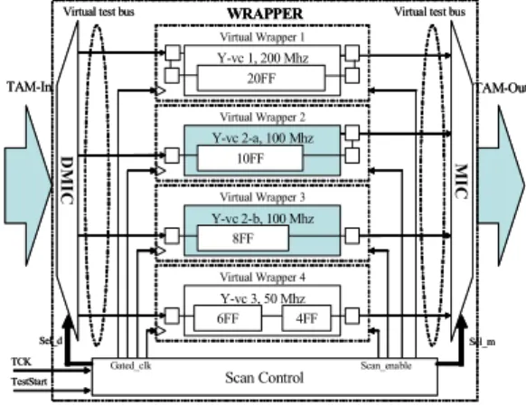
The basic architecture of the proposed multi-clock domain core wrapper is shown in Figure 1. The core is divided into smaller Y-vc’s, each having its own virtual wrapper. These Y-vc’s are connected to the external TAM via a pair of
de-multiplexing and multiplexing interface circuits (DMIC- MIC) which performs bandwidth matching and test data flow-control between the external TAM and the internal virtual test bus lines. The scan control circuitry for the proposed wrapper is shown in Figure 2. A capture window similar to that proposed in [8, 9] is used during the capture phase. We add a gate and MUX control circuit to control the clock signals during test as well as switch to the functional clocks during normal operation. A comparison of schedules obtained in [9], [10] and by our method is shown in Figure 3. The use of gated clocks enables a more flexible and efficient test schedule compared to the concurrent shifting in [9]. Instead of the shelf method in [10], our scheme allows partitioned testing with more flexibility during scheduling.
3 Problem Formulation
In this section, we formally present the wrapper design problem PMDCW.
Problem PMDCW: Given the test parameters for a multi-clock domain core C as described in section 2 and the information below:
Wext: TAM width allotted to the core fATE: ATE frequency
: The set of allowed shift frequencies
Determine the multi-clock domain wrapper design for C including:
Nvi: No. of virtual cores Y-vcip (1≦p≦Nvi) under domain Di
For each Y-vcip of clock domain Di
- fip∈F: Shift frequency - wip: No. of virtual bus lines
- Its wrapper scan chain design and the length of its longest scan chain lipmax
- tsip: Scan-in start time under the following constraints:
1) The bandwidth used by all the active Y-vc’s at any time t cannot exceed the total bandwidth coming from the ATE:
2) The total power dissipation of all active Y-vc’s at any time t cannot exceed the maximum allowed power dissipation Pmax:
such that the test application time is minimized. Since all the virtual cores become active and inactive independently, the total scan-shift time for one test pattern can be computed from the Y-vc with the latest end time as shown below:
Each Y-vc will have a distinct shift frequency and to simplify the clock generation circuitry, the ratio of usable frequencies is
} 1 ,..., 1 , 2
| ,..., ,
{ 1 2 = × 1 ∈ −
= f f f f f + j m
F m j j
Figure 1. Proposed multi-clock domain core wrapper
Virtual Wrapper 1 Y-vc 1, 200 Mhz
20FF
Virtual Wrapper 2 Y-vc 2-a, 100 Mhz
10FF
Virtual Wrapper 3 Y-vc 2-b, 100 Mhz
8FF
Virtual Wrapper 4 Y-vc 3, 50 Mhz
6FF 4FF
Virtual test bus
DMIC
Virtual test bus
MIC
Scan Control
Gated_clk Scan_enable
TAM-In TAM-Out
TCK TestStart
WRAPPER
Sel_d Sel_m
Virtual Wrapper 1 Y-vc 1, 200 Mhz
20FF
Virtual Wrapper 2 Y-vc 2-a, 100 Mhz
10FF
Virtual Wrapper 3 Y-vc 2-b, 100 Mhz
8FF
Virtual Wrapper 4 Y-vc 3, 50 Mhz
6FF 4FF
Virtual test bus
DMIC
Virtual test bus
MIC
Scan Control
Gated_clk Scan_enable
TAM-In TAM-Out
TCK TestStart
WRAPPER
Sel_d Sel_m
Capture FSM Clock Divider
Gate & MUX Control FSM MUX 0 1
MUX 0 1
MUX 0 1
f1 f2 fn
fcapture1 fcapture2
Test Start Clkext[1…m]
fcapturen Scan Enable [1…n]
Clk1 Clk2 Clkn
fATE
Figure 2. Proposed scan control circuit
) 2 ( max
1 1
max ≥ 0
∑ ∑
×= =
≤
≤
c vi
N
i N
p ATE
ip ip T ipt
t f
pow f a P
{
maxmax 0
1
1 1
0
:
) 1 ( max
f ) l f (t
|| t t , t
f ) l f
(t t ipt , t
N
i N
p
ip ip T ipt
ATE t ext
ip ip ATE sip sip
ip ip ATE sip sip
c vi
a where
w f a f
W
× +
>
<
×
≤ +
≤
= =
≤
≤
=
≥
×
∑ ∑
a two’s exponent. Our initial experiments have shown that completely dividing cores into sub-domains wouldn’t always yield shorter test times. Thus, we have developed a 3-D bin packing algorithm to determine how domains should be partitioned to minimize the scan-shift time T while also optimizing the number of virtual cores.
4 3-D Bin Packing Algorithm
Rectangular 2-D bin packing have been extensively used to solve the test scheduling problem for embedded cores [4]. For scheduling under a power constraint, it has been extended into a restricted 3-D bin packing problem where the length, width and height represent pin, peak power and total test time, respectively, for an SoC. Specifically, when a cube overlaps in the time domain, they cannot overlap at any of the other two domains. For this paper, instead of pin count, the length would represent the external bandwidth BWex=Wext × fATE and each virtual core of an IP-core C can be represented by one cube among a set of permissible cubes. The cubes are packed into the 3-D bin until all the sub-domains Sij of all the domains Di
have been included in the packed virtual cores while minimizing the total height. Since it has been shown that the restricted 3-D bin packing problem is NP-Hard in [12], this paper proposes a heuristic algorithm to solve the problem.
Initialization: Cube Creation and Ordering
Virtual cores can be created to represent any combination of sub-domains belonging to the same clock domain. Thus, if a domain Di has Nsi sub-domains, then the total number of possible virtual cores for Di is just the sum of all the possible combinations of Sij.
Single frequency wrapper design such as in [3] is performed on all virtual cores. We denote the maximum number of virtual test bus lines that can be assigned to a Y-vc as Vtbmax. Each virtual core can have a maximum of Vtbmax possible wrapper designs and the same number of cubes would be
created. From the list of cubes, the cube with the shortest test time regardless of power or bandwidth constraints would be selected as its ideal cube. It was proven in [10] that halving the shift frequency of the virtual core while doubling the virtual test bus width can result in either an increase in scan-shift time or no increase at all. We use this property to maintain the test time while still minimizing the power dissipation of the core. Each Y-vcip is expressed as a triplet Cip = {BWip, powip, tip}, where BWip = wip × fip is the bandwidth of Y-vcip, wip is the virtual test bus width assigned to it, and fip∈F is its shift frequency. Power dissipation powip at fip can be expressed as:
where f1 is the maximum allowed shift frequency. For this paper, we set f1= fATE and powipmax is the power dissipation at f1
as expressed below:
where bij = 1 when sub-domain Sij belongs to Y-vcip and bij = 0 if not. The minimum test time tip can be computed as follows:
The ideal cubes of virtual cores representing whole domains that satisfy the bandwidth and power restrictions is put into a list LM. The remaining ideal cubes not in LM but satisfy the bandwidth and power constraints are added to it. The ideal cubes of virtual cores representing only one sub-domain is then added to LM to ensure that all sub-domains would be scheduled.
An area attribute Aip = BWip × tip is also computed per virtual core of single sub-domains. Since the bigger the area attribute, the harder it is to pack, it follows that sub-domain groups which have big sub-domains must be prioritized by independently sorting LM from the virtual core which has the member sub-domain with the biggest area attribute to the smallest one. If two virtual cores have the same sized sub-domains, then the overall area attribute of the whole virtual cores are compared during sorting. After the list preparations, bin packing can be started from Step 1.
) 3 ( max
max max
1
1 + ×
= ≤≤ ≤ ≤ ip
ATE ip
N sip p N
i f
l f t T
vi c
∑
==
si
si N
j
j N
gi C
N
1
) 4 (
) 5 (
1 max
f f pow ip = pow ip × ip
) 6 (
1
max
∑
=
=
Nsi
j
ij ij
ip b pow
pow
) 7
max (
ip ip
ip f
t = l
Tim e t V C 3
f
V C4 V C2 B W
V C1
a
Tim e t V C 3
f
V C 4
V C 1b B W
V C1a
V C2
c
T im e t V C 3
f
V C 1
V C 4
V C 2 B W
ID LE
b
Figure 3. (a) concurrent scan in [9] (b) shelf method from [11] (c) using proposed method
Step 1: Packing of Domain Cubes
Before packing, the algorithm takes note of the current time in the schedule, denoted by a variable curr_time. The algorithm only divides domain Y-vc’s when necessary. In this step, the algorithm only looks at cubes representing whole domains in LM until it finds a cube that has powip ≦ powavail
and BWip ≦BWavail. powavail is the available power and BWavail
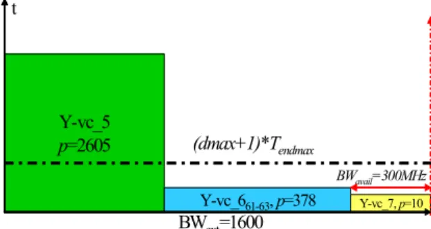
is the available bandwidth, respectively. If a cube is found and packed into the bin, the algorithm checks what sub-domains belong to it and updates LM by removing all cubes that has at least one member sub-domain equal to any of the sub-domains of the packed Y-vc. It continues the above process until (a) BWavail and/or powavail becomes zero or (b) if a proper cube cannot be found. Under condition (a), the algorithm looks among currently scheduled virtual cores for the Y-vc with the earliest test end time and sets curr_time equal to it. Then Step 1 is repeated. Under condition (b), the algorithm proceeds to Step 2. For the benchmark core hTCAD01[9] shown in Table 1 with BWext = 1600 and Pmax = 3000, Step 1 packs the Y-vc of domain no. 5 as shown in Figure 4.
Step 2: Packing of Sub-domain Group Cubes
Not finding a cube in Step 1 means that partitioning a domain is necessary. In this step the algorithm only looks at the cubes not tried in Step 1 (which represent sub-domain groups) until it finds a cube that has powip ≦ powavail and BWip ≦ BWavail. If a cube is found and packed into the bin, the algorithm again checks what sub-domains belong to it and updates LM. Step 2 is repeated while there is available power and bandwidth or if a proper cube cannot be found. If BWavail and/or powavail
become zero, curr_time is again updated and the algorithm goes back to Step 1. But if a proper cube cannot be found, the algorithm proceeds to Step 3. In Figure 4, Step 2 is illustrated when the Y-vc of sub-domain group S61 and S63 of domain no. 6 is packed into the bin.
Step 3: Filling Idle Space by Decreasing Virtual Test Bus Lines
In Step 3, the algorithm searches for the packed cube using the biggest bandwidth and denotes its test end time as Tendmax. LM is then traversed for a cube that satisfies the available power powavail. It then determines the new scan-shift time tipnew
given a new bandwidth BWipnew = BWavail. Because of the limited selection of usable shift frequencies, choosing the next lowest fk would automatically lead to a doubling of the scan-shift time. So for Step 3, the assigned virtual test bus width is decreased and tipnew is computed. The shift frequency is halved and the virtual test bus is doubled to minimize power as long as tipnew remains constant. If tipnew ≦ Tendmax×
(1+dmax/100) then the cube is packed into the bin and LM is updated as before. dmax is a heuristic value which expresses how much tipnew can go over Tendmax. The algorithm repeats Step 3 until there is no available bandwidth and/or power or no suitable cubes can be found. If BWavail and/or powavail become
zero, curr_time is updated and the algorithm goes back to Step 1. If no suitable cubes were found, the algorithm proceeds to Step 4. For example, the ideal cube of domain no. 7 has fip = 100MHz, wip = 15, powip = 40 and tip = 0.10μsec. In Figure 4, the idle bandwidth was 300MHz and for Y-vc_7, wip was first reduced to 3 at fip = 100MHz. Consequently tip increased to 0.48μsec. While keeping tip constant, we are able to increase the wip to 12, while decreasing the shift frequency fip to 25MHz and the power powip was lowered to 10 before packing the cube into the bin.
Step 4: Filling Idle Space by Decreasing Shift Frequency
Reaching Step 4 means that no cube satisfies the available power powavail. There is no choice but to lower the shift frequency of a virtual core to fit the available idle space in the bin. The algorithm determines Tendmax and makes a copy of LM
called Ltmp. Then the shift frequencies of all cubes remaining in Ltmp are lowered until their power is less than or equal to powavail.
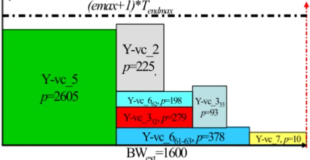
For each cube, the new scan-shift time tipnew is computed given a new bandwidth BWipnew = BWavail. The shift frequency is halved and the virtual test bus is doubled to minimize power as long as tipnew remains constant. Unlike Step 3, the algorithm looks for a cube that satisfies tipnew ≦ Tendmax×(1+emax/100) and closest to Tendmax as we have found during experimentation that this gives better results than simply packing the first cube that satisfies the first condition. The cube is packed into the bin and LM is updated as before. Step 4 is repeated until no cubes are found or until BWavail and/or powavail becomes zero. The algorithm then updates curr_time and goes back to Step 1. Note that emax is a heuristic value independent of dmax which expresses how much tipnew can go over Tendmax. Steps 1 through 4 are repeated until LM is empty. In Figure 5, although there is a large BWavail, pavail is only 302 so the fip of Y-vc_2 was decreased to 50MHz, and this led to a decrease in powip = 225 while wip remained the same and tip doubled to 3.00µsec. Figure 6 shows the finished schedule.
5 Experimental Results
Y-vc_5p=2605 t
BWext=1600
Y-vc_661-63, p=378 Y-vc_7, p=10
(dmax+1)*Tendmax
BWavail=300MHz
Figure 4. Packing results from steps 1 - 3
The experiments were done using the benchmark multi-clock domain core hTCADT01 used in [8, 9, 10]. This core has seven clock domains, and we assumed that each domain can be further partitioned into sub-domains as shown in Table 1. In the table, sd# denotes the sub-domain number, ffunc is the functional frequency, Nin, Nout , Nbi and Nsc are the number of inputs, outputs, bidirectional I/O and scan chains in the specific sub-domain respectively, Lscij is the length of each scan chain and P is the power dissipation of the sub-domains when shifting at 100MHz and is the sum of all the scan chain lengths Lscij belonging to that sub-domain.
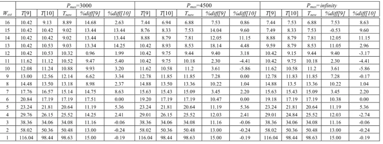
The experiment was conducted under four different power constraints Pmax: 1500, 3000, 4500 and infinity. The maximum allowed frequency f1 is 100MHz which is equal to fATE. to synchronize the internal shift frequencies with the ATE. To see the effectiveness of the proposed method, the resulting shift times denoted by Tnew are compared to the results from [9], marked T[9], and from [10], marked T[10], in Tables 2 and 3. All times are in microseconds. %diff[9] and %diff[10] are the differences in percentage to [9] and [10] respectively.
During the experiments, dmax and emax were independently varied from 0 to 200 to find the optimal combination. The experiments were done using a Sun Fire V490 1.35GHz UltraSPARC IV workstation with 32GB memory and the 40,000 looped reruns of the program didn’t take more than 1 sec. of CPU time.
At the tightest power constraint Pmax = 1500, our algorithm was able to decrease the shift time with a maximum of 24.42% compared to [9]. The average gain in test time as Pmax is decreased, increases dramatically from 8.69% at Pmax = infinity to 18.36% at Pmax = 1500. This can be attributed to the fact that wider Wext and lower Pmax makes splitting the domains more effective because of the extra freedom it gives during scheduling. Compared to [10], the trend is different and there is an almost constant average gain of around 4% across all power constraints and a maximum gain of 14.25% at Pmax = 3000. Small differences in time (0-1%) are attributed to discrepancies in rounding-off among the programs used and makes them negligible, so our algorithm matches or exceeds [10] in 90% of the cases.
In [8, 9], the area of the scan control block was stated to be less than 10% the area size taken by the IEEE 1500 wrapper and other scan logic. Since our approach only requires a slight modification of the scan control circuitry in [8, 9], it is safe to assume that the added overhead would be minimal. Furthermore, as manufacturing processes become smaller and transistor count becomes higher, the probable DFT overhead becomes more and more negligible in light of the possible gains in test application time. Also, the added flexibility of domain partitioning and partitioned test scheduling would be of greater benefit as designers start to re-use older generation multi-clock domain circuits as IP-cores in newer, more complex designs.
6 Conclusion
We have presented a novel method of designing a test wrapper for multi-clock domain cores by effectively utilizing clock domain partitioning and gated-clocks. With minimal hardware overhead for gated-clock control, we have dramatically improved upon earlier methods which concurrently activate all the domains during test, especially under tight power constraints. Furthermore, the division of clock domains enabled us to give better results than the previous methods with comparable hardware overhead.
Acknowledgements
This work was supported in part by Japan Society for the Promotion of Science (JSPS) under Grants-in-Aid for Scientific Research B(2)(No.15300018), JSPS under Grants-in-Aid for Young Scientists (B) (No. 18700046) and the grant of JSPS Research Fellowship (No. S06089).
References
[1] E. J. Marinissen, S. K. Goel and M. Lousberg, “Wrapper Design for Embedded Core Test,” Proc. of IEEE International Test Conference (ITC), pp. 911–920, 2000.
Y-vc_5 p=2605 t
BWext=1600 Y-vc_661-63, p=378
Y-vc_333 p=93
Y-vc_7, p=10 Y-vc_662, p=198
Y-vc_2 p=225,
Y-vc_332, p=279
(emax+1)*Tendmax
Figure 5. Cube of domain 2 packed in step 4 Y-vc_5
p=2605 t
BWext=1600 Y-vc_661-63, p=378
Y-vc_111, p=668
Y-vc_4, p=1314
Y-vc_662, p=198
Y-vc_2 p=225,
Y-vc_332, p=279 Y-vc_112, p=652
Y-vc_113, p=648 Y-vc_114, p=604
Y-vc_311, p=465
Y-vc_7, p=10 Y-vc_333
p=93
Figure 6. Finished test schedule for hTCAD01 at with BWext = 1600 and Pmax = 3000
[2] S. K. Goel and E. J. Marinissen, “Effective and Efficient Test Architecture Design for SoCs,” Proc. of IEEE International Test Conference (ITC), pp. 529–538, 2002.
[3] V. Iyengar, K. Chakrabarty and E. J. Marinissen, “Test Wrapper and Test Access Mechanism Co- Optimization for System-on-Chip,” Journal of Electronic Testing: Theory and Application, vol. 18, pp. 213–230, April 2002.
[4] V. Iyengar, K. Chakrabarty and E. J. Marinissen, “Test Access Mechanism Optimization, Test Scheduling, and Tester Data Volume Reduction for System-on-Chip,” IEEE Trans. On Computers, vol. 52, no. 12, pp. 1619–1632, December 2003. [5] G. Hetherington, T. Fryars, N. Tamarapalli, M. Kassab, A.
Hassan and J. Rajski, “Logic BIST for Large Industrial Designs: Real Issues and Case Studies,” Proc. of IEEE International Test Conference (ITC), pp. 358–367, 1999.
[6] K. Hatayama, M. Nakao and Y. Sato, “At- Speed Built-in Test for Logic Circuits with Multiple Clocks,” Proc. of the 11th Asian Test Symposium (ATS), pp. 292–297, 2002.
[7] V. Jain and J. Waicukauski, “Scan Test Volume Reduction in Multi-Clocked Designs with Safe Capture Technique,” Proc. of IEEE International Test Conference (ITC), pp. 148–153, 2002. [8] Q. Xu and N. Nicolici, “Wrapper Design for Testing IP Cores
with Multiple Clock Domains,” Proc. of Design, Automation, and Test in Europe (DATE), pp. 416–421, 2004.
[9] Q. Xu, N. Nicolici and K. Chakrabarty, “Multi-Frequency Wrapper Design and Optimization for Embedded Cores Under Average Power Constraints,” Proc. of ACM/IEEE Design Automation Conference (DAC), pp. 123–128, 2005.
[10] D. Zhao, and U. Chandran, “Design of A Time-Gated Multi-Frequency Wrapper Architecture for Modular SoC Testing,” Proc. of IEEE 15th North Atlantic Test Workshop (NATW), May 2006.
[11] Y. Xia, M. Chrzanowska-Jeske, B. Wang and M. Jeske, “Using a Distributed Rectangle Bin-Packing Approach for Core-based SoC Test Scheduling with Power Constraints,” Proc. Of the International Conference on Computer-Aided Design (ICCAD), pp. 100–105, 2003.
[12] Y. Huang et al., “Optimal Core Wrapper Width Selection and SOC Test Scheduling Based on 3-D Bin Packing Algorithm,” Proc. of IEEE International Test Conference (ITC), pp. 74–82, 2002.
sd# ffunc
(MHz) Nin Nout Nbi P Nsc Lscij
1.1 200 50 8 18 668 4 168 168 166 166
1.2 200 25 8 18 652 4 163 163 163 163
1.3 200 25 8 18 648 4 162 162 162 162
1.4 200 9 8 18 604 4 151 151 151 151
2.1 133 144 67 72 450 3 150 150 150
3.1 120 39 4 24 465 5 93 93 93 93 93
3.2 120 30 3 24 279 3 93 93 93
3.3 120 20 1 24 186 2 93 93
4.1 75 61 10 36 657 3 219 219 219
4.2 75 50 21 36 657 3 219 219 219
5.1 50 87 200 36 1563 3 521 521 521
5.2 50 30 24 36 1042 2 521 521
6.1 33 96 10 24 278 5 82 81 81 17 17
6.2 33 30 18 24 198 4 82 81 18 17
6.3 33 20 40 24 100 2 82 18
7.1 25 15 30 72 40 4 10 10 10 10
Pmax=1500
Wext T[9] T[10] Tnew %diff[9] %diff[10]
16 20.84 16.9 15.75 24.42 6.80
15 20.84 16.9 15.75 24.42 6.80
14 20.84 16.9 15.75 24.42 6.80
13 20.84 16.9 15.75 24.42 6.80
12 20.84 16.9 15.85 23.94 6.21
11 20.84 16.97 15.85 23.94 6.60
10 20.84 17.07 16.68 19.96 2.28
9 20.84 17.47 15.91 23.66 8.93
8 20.84 17.57 16.9 18.91 3.81
7 20.84 19.29 18.92 9.21 1.92
6 20.84 19.6 19.63 5.81 -0.15
5 25.04 23.38 23.19 7.39 0.81
4 29.76 26.16 25.34 14.85 3.13
3 41.68 34.06 34.08 18.23 -0.06
2 59.88 51.61 50.81 15.15 1.55
1 116.04 100.7 98.69 14.95 2.00
Pmax=3000 Pmax=4500 Pmax=infinity
Wext T[9] T[10] Tnew %diff[9] %diff[10] T[9] T[10] Tnew %diff[9] %diff[10] T[9] T[10] Tnew %diff[9] %diff[10]
16 10.42 9.13 8.89 14.68 2.63 7.44 6.94 6.88 7.53 0.86 7.44 7.53 6.88 7.53 8.63
15 10.42 10.42 9.02 13.44 13.44 8.76 8.33 7.53 14.04 9.60 7.49 8.33 7.53 -0.53 9.60 14 10.42 10.42 9.02 13.44 13.44 8.88 8.79 7.81 12.05 11.15 8.88 8.79 7.81 12.05 11.15 13 10.42 10.53 9.03 13.34 14.25 10.42 8.93 8.53 18.14 4.48 9.59 8.79 8.53 11.05 2.96
12 10.42 10.53 10.32 0.96 1.99 10.42 9.75 9.44 9.40 3.18 10.42 9.15 9.44 9.40 -3.17
11 11.62 11.12 10.52 9.47 5.40 10.42 9.75 10.18 2.30 -4.41 10.42 9.75 10.18 2.30 -4.41
10 12.08 11.24 10.88 9.93 3.20 11.62 10.58 11.2 3.61 -5.86 11.62 10.58 11.2 3.61 -5.86
9 13.00 12.56 12.14 6.62 3.34 12.78 11.85 11.85 7.28 0.00 12.78 11.83 11.85 7.28 -0.17
8 14.48 13.50 13.18 8.98 2.37 14.88 13.50 13.36 10.22 1.04 14.88 13.5 13.36 10.22 1.04
7 17.76 16.57 15.14 14.75 8.63 15.63 15.43 15.09 3.45 2.20 15.63 15.43 15.09 3.45 2.20
6 20.84 17.19 17.19 17.51 0.00 19.20 17.19 17.19 10.47 0.00 19.18 17.19 17.19 10.38 0.00 5 23.24 21.81 20.64 11.19 5.36 23.24 21.81 20.64 11.19 5.36 23.24 21.81 20.64 11.19 5.36 4 29.76 26.15 25.52 14.25 2.41 29.01 26.15 25.52 12.03 2.41 29.01 24.84 25.52 12.03 -2.74 3 38.36 34.06 34.08 11.16 -0.06 38.36 34.06 34.08 11.16 -0.06 38.36 34.06 34.08 11.16 -0.06 2 58.02 50.36 50.48 13.00 -0.24 58.02 50.36 50.48 13.00 -0.24 58.02 50.36 50.48 13.00 -0.24 1 116.04 98.44 98.63 15.00 -0.19 116.04 98.44 98.63 15.00 -0.19 116.04 98.44 98.63 15.00 -0.19
Table 1. hCADT01 clock and sub-domain information
Table 2. Comparison of Scan-shift Time for hCADT01 under Pmax = 1500
Table 3. Comparison of Scan-shift Time for hCADT01 under Pmax = 3000, 4500 and infinity
![Figure 3. (a) concurrent scan in [9] (b) shelf method from [11] (c) using proposed method](https://thumb-ap.123doks.com/thumbv2/123deta/5752809.27054/3.892.111.783.290.440/figure-concurrent-scan-shelf-method-using-proposed-method.webp)