精密機械カンパニー
東京本社
〒105-8315 東京都港区海岸1丁目14-5 Tel. 03-3435-6862 Fax. 03-3435-2023 神戸本社
〒650-8680 神戸市中央区東川崎町1丁目1-3(神戸クリスタルタワー) Tel. 078-360-8605 Fax. 078-360-8609
西神戸工場
〒651-2239 神戸市西区櫨谷町松本234番地 Tel. 078-991-1133 Fax. 078-991-3186 福岡営業所
〒812-0011 福岡市博多区博多駅前1丁目4-1(博多駅前第一生命ビルディング9F)
Tel. 092-432-9561 Fax. 092-432-9566 東京サービスセンター
〒272-0015 千葉県市川市鬼高4丁目9-2 Tel. 047-379-8181 Fax. 047-379-8186 今治サービスセンター
〒794-0028 愛媛県今治市北宝来町1丁目5-3(ジブラルタ生命ビル、川重商事内) Tel. 0898-22-2531 Fax. 0898-22-2183
福岡サービスセンター
〒811-0112 福岡県粕屋郡新宮町下府2丁目10-17 Tel. 092-963-0452 Fax. 092-963-2755
http://www.khi.co.jp/kpm/
Cat. No. KPM1410 Oct. '14 S 精密機械カンパニー
Kawasaki Precision Machinery (UK) Ltd.
Ernesettle Lane, Ernesettle, Plymouth, Devon, PL5 2SA United Kingdom Phone +44-1752-364394 Fax. +44-1752-364816
http://www.kpm-eu.com
Kawasaki Precision Machinery (U.S.A.), Inc.
3838 Broadmoor Avenue S.E. Grand Rapids, Michigan 49512, U.S.A. Phone +1-616-975-3100 Fax. +1-616-975-3103
http://www.kpm-usa.com
Kawasaki Precision Machinery (Suzhou) Ltd.
668 JianLin Rd, New District, Suzhou, 215151 China Phone +86-512-6616-0365 Fax. +86-512-6616-0366
Kawasaki Precision Machinery Trading (Shanghai) Co., Ltd.
17th Floor (Room 1701), The Headquarters Building, No168, XiZang Road (M), Huangpu District, Shanghai, 200001, China
Phone +86-021-3366-3800 Fax. +86-021-3366-3808
Kawasaki Chunhui Precision Machinery (Zhejiang) Ltd.
No.200 Yasha Road Shangyu Economic Development Zone, Shansyu, Zhejiang, 312300, China
Phone +86-575-8215-6999 Fax. +86-575-8215-8699
Flutek, Ltd.
98 GIL 6, Gongdan-Ro, Seongsan-Ku, Changwon-Si, Kyungnam,641-370, Korea Phone +82-55-210-5900 Fax. +82-55-286-5557
Wipro Kawasaki Precision Machinery Private Limited
No. 15, Sy. No. 35 & 37, Kumbalgodu Industrial Area, Kumbalgodu Village, Kengeri Hobli, Bangalore, – 560074 ,India
Tokyo Head Office
1-14-5 Kaigan, Minato-ku, Tokyo 105-8315, Japan Phone +81-3-3435-6862 Fax. +81-3-3435-2023
Kobe Head Office
Kobe Crystal Tower, 1-3 Higashikawasaki-cho 1-chome, Chuo-ku, Kobe 650-8680, Japan
Phone +81-78-360-8607 Fax. +81-78-360-8609
Nishi-kobe Works
234, Matsumoto, Hasetani-cho, Nishi-ku, Kobe 651-2239, Japan Phone +81-78-991-1160 Fax. +81-78-991-3186
Precision Machinery Company
OVERSEAS SUBSIDIARIES
http://www.khi.co.jp/kpm/
精密ギヤポンプ
Precision Gear Pumps
このカタログに記載の内容は、改良のため予告なく改訂・変更する場合があります。
■もくじ/CONTENTS
川崎重工業(株)では、
1946
年から高精密ギヤポンプ
の生産を開始。以来、世界各国に送り出しており、その
性能は高い評価を得ています。
このカワサキ精密ギヤポンプは、
もともと吐出脈動が少
なく定量性の良い外接型ギヤポンプをベースに、その製
作精度を高めて、
より高次元の性能を追求したものです。
まず、化学繊維製造における紡糸ノズルへの計量圧送
用として開発され、現在では、その優れた性能と特長によっ
て、多くの用途にご使用いただいています。
Kawasaki Heavy Industries, Ltd. has been
manufac-turing precision gear pumps since 1946, and their
performance is highly acclaimed worldwide.
The Kawasaki Precision Gear Pumps are
pro-duced with the enhanced manufacturing accuracy to
improve performance of the external-contact type
gear pumps, which have small pulsations and good
volumertic characteristics. Those pumps were
origi-nally developed for pumping and metering of
poly-mer to the spinnerette in the production of chemical
fibers, and have prevailed in many other applications.
精密ギヤポンプ
PRECISION GEAR PUMP
Page
概要/OUTLINE ……… 2
ギヤポンプの原理/PRINCIPLE OF OPERATION OF THE GEAR PUMP …… 3
特長/FEATURES ポンプシリーズ外観/APPEARANCE 形式表示/TYPE NOTATION ……… 4
仕様および選定/SPECIFICATIONS AND SELECTION ……… 5
取扱上の注意/CAUTIONS FOR HANDLING(Do and Don't) ……… 9
KAP-1/KA1 SERIES ……… 15
KA3SERIES ……… 17
KA4SERIES ……… 19
BASSERIES ……… 21
BAS-HSERIES ……… 23
KH5SERIES ……… 25
KESSERIES ……… 27
PFSSERIES ……… 29
KHP-1HSERIES ……… 31
HFSERIES ……… 33
HBSERIES ……… 35
HBTSERIES ……… 37
HBTDSERIES……… 39
HBTDSSERIES……… 41
HTSERIES ……… 43
BSERIES……… 45
ギヤポンプ装置例/TYPICAL INSTALLATION ……… 47
シャーピン付カップリング/SHEAR PIN COUPLING ……… 48
トルクレリーサー/TORQUE RELEASER ボールジョイント/BALL JOINT ジャケット/JACKET ……… 49
アルミ鋳込ヒーター/ALUMNUM-CAST HEATER ポンプブロック/PUMP BLOCK ……… 50
引合仕様書/INQUIRY SPECIFICATION ……… 51
安全上の注意事項/SAFETY PRECAUTIONS……… 53
HT
800
C
G
J
02
H
■ 特長
カワサキ精密ギヤポンプの主な特長は以下の通りです。
【高い吐出精度】
高い容積効率によって、圧力や粘度の変動がある場合でも安定し た吐出量を得ることができます。この吐出精度は高い加工精度に 裏づけられており、また、各部品は互換性を有しています。
【長い寿命】
厳選された素材と、それに適した熱処理によって、長い寿命を持た せています。
【広い適用範囲】
豊富な機種構成によって、広範囲な用途への適用を可能にしてい ます。
■ポンプシリーズ外観/APPEARANCE
■
FEATURES
Main Features of Kawasaki Precision Gear Pump are as follows.
【
High Accuracy of Discharge Volume
】High volumetric efficiency enables a stable output flow despite fluctuations in pressure and/or viscosity. The high accuracy is ensured by extremely accurate finishing. Each component is designed to be interchangeable.
【
Long Durability
】Long durability is ensured with careful selection of pump materials and adequate heat treatment for them.
【
Wide Application Ranges
】Abundance of type enables variety of applications.
■ギヤポンプの原理/PRINCIPLE OF OPERATION OF THE GEAR PUMP
■形式表示/TYPE NOTATION
入口部で、回転により歯車の噛み合
いが離れるとき、歯溝に液体が吸い
込まれます。
この歯溝にたまった液体は、ケーシ
ングと側板によって閉じ込められ、回
転に従ってケーシングの内側に沿っ
て出口部の方向に移動します。
出口部で、ギヤの歯の噛み合わせに
よって、液体が押し出されます。
Liquid is filled in grooves of the revolving gears at the inlet, when the gears are disengaged.
The liquid confined in the cavities formed by the gear teeth, gear casing and side plates moves along the internal circumferential of the casing towards the outlet.
The liquid is displaced by the meshing of the gear teeth at the outlet.
このようにギヤポンプは、一定の流量が得られる定容積型ポ
ンプです。構造が簡単で、かつ低脈動、さらに高い精度で製
作可能という特長を持っています。
Gear pump is a positive displacement pump. It is of
simple construction, yet providing low pulsation, and
can be very accurately fabricated.
KAP-1/KA1
series
KA3
series
KA4
series
BAS
series
BAS-H
series
KH5
series
KES
series
KHP-1H
series
HF
series
HB
series
HBT
series
HBTD
series
HBTDS
series
HT
series
B
series
PFS
series
■シリーズ名称
Series code
■押しのけ容積(cm3)
Displacement
■ギヤ材質 Gear material
F:構造用鋼
Steel for general structure C:工具鋼
Tool steel S:耐食・耐摩耗合金
Wear-resistant, corrosion-resistant alloy
■下記シリーズは無記号
Omitted for series below
KAP-1, KA1, KA3, KA4, BAS, BAS-H, KH5, KES, PFS, KHP-1H
■BAS-H 高圧用
Modified version for higher pressure applications (BAS-H)
■回転方向・設計番号
Rotation direction, Design number
偶数 :右回転 Even number:clockwise 奇数 :左回転 Odd number:Counter clockwise
(Viewed from shaft end)
■軸封形式 Shaft seal type
G:グランドパッキン Gland packing
M:メカニカルシール、メタルシール、リングシール Mechanical seal, Metal seal, Ring seal Z:その他、または無し
Others or non
■ジャケットの有無
Heating jacket
■仕様および選定/SPECIFICATION AND SELECTION
カワサキ精密ギヤポンプは、繊維分野と同様に化学工業分野でも広く使用されています。
用途、吐出量、粘度により下表からポンプシリーズをご選定ください。
なお、各シリーズの詳細につきましては次ページ以降のデータをご利用ください。
The Kawasaki Precision Gear Pumps have been used in various chemical
industries as well as chemical fiber areas. Please select optimum series according
to your application, required throughput, pressure, and viscosity.
See the pages following for the details of each series.
注記 :
1)○は使用可能、◎はその用途に適したポンプシリーズを示します。 2)化学繊維用については別カタログをご参照ください。
3)ポンプ回転速度と最高吐出圧力は、液の粘度により制限されます。 7ページの表1をご参照ください。
4)温度により使用材料が替わります。
5)取付方法については7ページの表2をご参照ください。 6)軸封については8ページの表3をご参照ください。
7)耐食・耐摩耗材の場合は、3.92 MPa(40kgf/cm2)となります。
Note :
1)○: Acceptable for the use.
◎: Adequate choice for the application.
2)See the special catalog for chemical fiber applications.
3)Pump speed and all allowed max. pressure are restricted by the viscosity of liquid. See Table 1 (page 7) .
4)Different materials are used depending on temperature. 5)See Table 2 (page 7) for mounting method.
6)See Table 3 (page 8) for shaft seal type.
7)Max. differential pressure is 3.92 MPa (40 kgf/cm2) with the wear-resistant, corrosion-resistant material. KA3 KA4 BAS BAS-H KH5 KES PFS KHP-1H HF HB HBT HBTD HBTDS HT B KAP-1 KA1
1) 用 途/Application 3) 容 量 範 囲/Capacity range 適用範囲/Applicable range
シ
リ
ー
ズ
コ
ー
ド
計
量
︵
︶
塗料 薬液 乳剤 溶剤 バター
押
出
成
形
高
品
位
成
形
重
合
真
空
抜
出
し
化
学
繊
維
2) Series code Metering (paints chemicals emulsion, solvents, butter) Extrusion molding
High quality molding Polycondensation Vacuum discharge
Chemical fiber
最
高
温
度
4)
Max. temperature
最
大
吐
出
圧
力
3)
Max. outlet pressure
最
大
差
圧
3)
Max. differential
pressure
最
大
粘
度 Max. viscosity
℃ (kgf/cmMPa2) (kgf/cmMPa2) (Poise)Pa・s
ポンプ 押しのけ容積 Pump capacity
cm3
5)
取 付 方 法 Mounting
6)
軸 封 Shaft seal type
材 料 Material
0.5 1 2 5 10 20 50 100
L / min
0.015 ∼ 0.6 L /min
0.03 ∼ 1.1 L /min
0.15 ∼ 4.5 L /min
0.06 ∼ 3 L /min
0.06 ∼ 2 L /min
0.2 ∼ 6 L /min
0.8 ∼ 20 L /min
0.25 ∼ 15 L /min
0.001 ∼ 0.24 L /min
0.1 ∼ 40 L /min
2 ∼ 60 L /min
0.1 ∼ 90 L /min
0.1 ∼ 72 L /min
0.1 ∼ 40 L /min
0.02 ∼ 160 L /min
3 ∼ 800 L /min
0.06 0.15 1.168 0.297 1.752 0.584 2.92
3, 5, 7.6
15, 30 6, 7.2, 10 12, 15 20, 30 6, 7.2, 10, 20 40 50 60 80 100 150 200 50 80 100 150
0.1 0.15 0.3 0.6 1.2 1.6 2.4 3 4 5 6
10.0∼ 800
200.0∼ 1,500
10.0∼ 2,250
10.0∼ 1,800
10.0∼ 400
2.5∼ 4,000
300.0∼ 40,000
120 120 120 120/350 120/350 120/350 120/350 120 350 350 350 350 350 120 350 120 6.9(70) 6.9(70) 2.9(30) 49(500) 19.6(200) 14.7(150) 7.8(80) 49(500) 39.2(400) 29.4(300) 2.94(30) 29.4(300) 4.9(50) 29.4(300) 24.5(250) 19.6(200) 39.2(400) 19.6(200) 14.7(150) 7.8(80) 39.2(400) 29.4(300) 29.4(300) 2.94(30) 24.5(250) 4.9(50) 100 (1,000) 100 (1,000) 100 (1,000) 1,000 (10,000) 1,000 (10,000) 100 (1,000) 400 (4,000) 100 (1,000) 400 (4,000) 10,000 (100,000) 5,000 (50,000) 1,000 (10,000) 1,000 (10,000) 10 (100) 10,000 (100,000) 200 (2,000) 19.6(200) 14.7(150) 9.8(100) 7) 6.9/3.9 (70/40)
サドル取付 Saddle mounting
ブロック取付 Block mounting
配管取付 Pipe mounting
ブロック取付 Block mounting
タンク/台板取付 Tank/Foot mounting 台板取付 Foot mounting
特殊メカニカルシール(○) Special mechanical seal
a
標準 : Standard :
グランドパッキン(○) Gland packing オプション : Option :
メカニカルシール(○) Mechanical seal シーリングカプラー(○) Sealing coupler メタルシール(○) Metal seal メタルシール + グランドパッキン(○) Metal seal + Gland packing b c d e g
シーリングカプラー(○) Sealing coupler d メタルシール(○) Metal seal
e
グランドパッキン(○) Gland packing
c
グランドパッキン(○) Gland packing リングシール(○)
Ring seal c f
グランドパッキン(○) Gland packing
c メカニカルシール(○) Mechanical seal b グランドパッキン(○) Gland packing
リングシール(○)/Ring seal c f
KAP-1
KA3 ステンレス鋼 KA4 Stainless Steel KA1
KA3 KA4
ギヤ : 耐食・耐摩耗合金 Gears Wear-resistant,
corrosion-resistant material シャフト・ボディ:耐食・耐摩耗合金盛り
Shafts and body Coated by wear-resistant, corrosion-resistant material
120℃以下用 :ステンレス鋼 For Max. 120 ℃ Stainless steel 350℃以下用 : 合金工具鋼 For Max. 350 ℃ Alloy tool steel
ギヤ :耐食・耐摩耗合金
Gears Wear-resistant, corrosion-resistant material シャフト・ボディ:耐食・耐摩耗合金盛り
Shafts and body Coated by wear-resistant,corrosion-resistant material
高速度工具鋼 High speed tool steel
合金工具鋼 Alloy tool steel
ギヤ・シャフト :合金工具鋼
Gears and shafts Alloy tool steel
本体 :ステンレス鋼
Body Stainless steel
接液摺動部・接液部 :ステンレス鋼
Wet and wearing parts, Wet body Stainless steel
非接液部 :鋳鉄
Non-wet body Cast iron
2.9(30)
◆
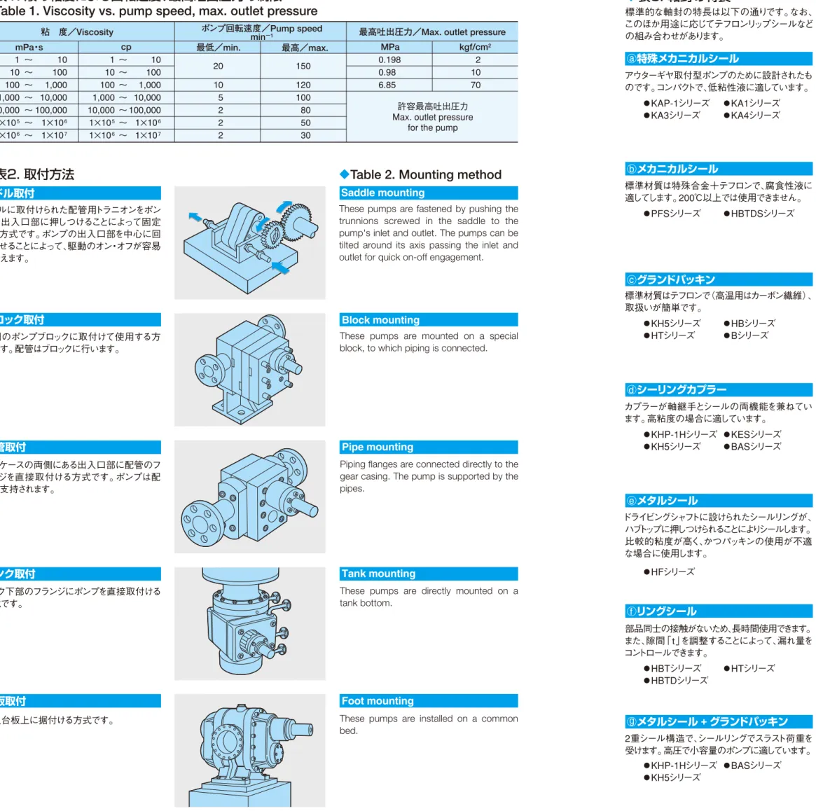
表1. 液の粘度による回転速度、最高吐出圧力の制限
Table 1. Viscosity vs. pump speed, max. outlet pressure
◆
表2. 取付方法
◆
Table 2. Mounting method
Block mounting
Saddle mounting
Tank mounting
Foot mounting
These pumps are fastened by pushing the trunnions screwed in the saddle to the pump's inlet and outlet. The pumps can be tilted around its axis passing the inlet and outlet for quick on-off engagement.
These pumps are mounted on a special block, to which piping is connected.
These pumps are installed on a common bed.
These pumps are directly mounted on a tank bottom.
Pipe mounting
Piping flanges are connected directly to the gear casing. The pump is supported by the pipes.
サドル取付
ブロック取付
配管取付
タンク取付
台板取付
サドルに取付けられた配管用トラニオンをポン プの出入口部に押しつけることによって固定 する方式です。ポンプの出入口部を中心に回 転させることによって、駆動のオン・オフが容易 に行えます。
専用のポンプブロックに取付けて使用する方 式です。配管はブロックに行います。
ギヤケースの両側にある出入口部に配管のフ ランジを直接取付ける方式です。ポンプは配 管で支持されます。
タンク下部のフランジにポンプを直接取付ける 方式です。
共通台板上に据付ける方式です。
○
Sealing Coupler
Features of shaft-seals are as follows. Such special seals as teflon lip seal, etc. are also available.
◆
表3. 軸封の特長
◆
Table 3. Features of shaft-seal
標準的な軸封の特長は以下の通りです。なお、 このほか用途に応じてテフロンリップシールなど の組み合わせがあります。
○
Special Mechanical Seal
○
Gland Packing
○
Ring Seal
○
Metal Seal + Gland Packing
○
Metal Seal
○
Mechanical Seal
The coupler functions as both coupling and seals. It is appropriate for high viscosities. This seal has been designed for outer-gear drive pumps. It is compact and suitable for low viscosity liquids.
Teflon is standard packing material. (Carbon-fiber is used for high temperature applica-tions.) This is simple and easy to handle.
Long durability is ensured since there are no frictional parts. Leakage can be controlled by adjusting the clearance "t".
This is a double seal and thrust force is sup-ported by the seal ring. This is suitable for a pump of small capacity under high pressure use.
Standard combination of material is special alloy and teflon. This seal is suitable for corrosive liquids but can not be used above
200℃.
Sealing function is performed when the seal-ring, installed on the driving shaft, is pushed against the hub top. This is used when viscosity is high and a gland packing is not appropriate.
a
b
c
d
e
f
g
●KAP-1 Series ●KA1 Series ●KA3 Series ●KA4 Series
●PFS Series ●HBTDS Series
●KH5 Series ●HB Series ●HT Series ●B Series
●KHP-1H Series ●KES Series ●KH5 Series ●BAS Series
●HF Series
●HBT Series ●HT Series ●HBTD Series
●KHP-1H Series ●BAS Series ●KH5 Series
○特殊メカニカルシール
a○メカニカルシール
b○グランドパッキン
c○シーリングカプラー
d○メタルシール
e○リングシール
f○メタルシール
g+
グランドパッキン
アウターギヤ取付型ポンプのために設計されたも のです。コンパクトで、低粘性液に適しています。
●KAP-1シリーズ ●KA1シリーズ ●KA3シリーズ ●KA4シリーズ
標準材質は特殊合金+テフロンで、腐食性液に 適してします。200℃以上では使用できません。
●PFSシリーズ ●HBTDSシリーズ
標準材質はテフロンで(高温用はカーボン繊維)、 取扱いが簡単です。
●KH5シリーズ ●HBシリーズ ●HTシリーズ ●Bシリーズ
カプラーが軸継手とシールの両機能を兼ねてい ます。高粘度の場合に適しています。
●KHP-1Hシリーズ ●KESシリーズ ●KH5シリーズ ●BASシリーズ
ドライビングシャフトに設けられたシールリングが、 ハブトップに押しつけられることによりシールします。 比較的粘度が高く、かつパッキンの使用が不適 な場合に使用します。
●HFシリーズ
部品同士の接触がないため、長時間使用できます。 また、隙間「t」を調整することによって、漏れ量を コントロールできます。
●HBTシリーズ ●HTシリーズ ●HBTDシリーズ
2重シール構造で、シールリングでスラスト荷重を 受けます。高圧で小容量のポンプに適しています。
●KHP-1Hシリーズ ●BASシリーズ ●KH5シリーズ
1 ∼ 10 1∼ 10
20 150 0.198 2
10 ∼ 100 10∼ 100 0.98 10
100 ∼ 1,000 100∼ 1,000 10 120 6.85 70
1,000 ∼ 10,000 1,000∼ 10,000 5 100
10,000 ∼100,000 10,000∼100,000 2 80
1×10⁵ ∼ 1×10⁶ 1×10⁵∼ 1×10⁶ 2 50
1×10⁶ ∼ 1×10⁷ 1×10⁶∼ 1×10⁷ 2 30
粘 度/Viscosity ポンプ回転速度/Pump speedmin−1
最低/min. 最高/max.
最高吐出圧力/Max. outlet pressure MPa kgf/cm2
許容最高吐出圧力 Max. outlet pressure
for the pump
mPa・s cp
●仕様に適合するポンプを選定してください。
●ご使用前に必ず取扱説明書をお読みください。
●フィルタ(できれば200メッシュ以上のもの)を使用し、ポンプ の中に未溶融物や異物が入らないようにしてください。
●ポンプの入口、出口を確認して配管してください。(通常は口 径の大きいほうが入口です)
●高温で使用する場合は、フレキシブルジョイントで芯ズレを吸 収してください。なお、常温使用の場合、許容芯ズレは下記 の値以下にしてください。
取扱上の注意
(安全上の注意事項については、53ページをご覧ください。)
《してください》
《しないでください》
1. 全般注意事項
●異常トルクがかかったときの保護対策として、モータ電流値を 必ず設定し、シャーピン、トルクリミッタなどをご採用ください。
●ポンプとポンプブロック間の漏れを防ぐため、締めつけボルトは、 ネジ面に焼付防止剤(DAG #580、モリコート、ネバーシーズ など)を塗布してから、必ず指定のトルクで締めつけてください。
●カプラシール型の場合、
○1 駆動用軸は、1°、0.1mm以内の平行度に芯出ししてくださ い。また、軸封機能が正常に働くよう、駆動軸がカプラを 押さないようにご注意ください。
○2 ハブトップとカプラの間には、ポリマー潤滑が始まる前の潤 滑のために、蒸発しにくく耐熱性のある潤滑油(モリコート、 ネバーシーズなど)を塗布してください。
●ポンプのスタートは最低速から行なってください。
●回転方向をご確認ください。(ポンプに刻印してある矢印に従っ てください)
●はじめて運転するとき、または1度停止したあと再び運転する ときには、ドライビングシャフトを手回しして、軽く回転すること をご確認ください。
●当社の精密ギヤポンプは、通常、内部に防錆と初期潤滑を 兼ねて耐熱シリコンオイルが封入されていますが、長期間 (6ヵ月以上)保管してあったポンプを使用するときには、ポン プ入口からシリコンオイルを再度注入し、ドライビングシャフト を手回ししてオイルをポンプ全体に行き渡らせてください。
●ポンプ停止時に、液が固化・変質するおそれがある場合は、 安定した液と置換する、ポンプを取り外して溶剤に浸ける、ポ ンプを分解洗浄する、などの適切な手段を講じてください。
●ポンプを長時間保存する場合は、内部に防錆油(通常は東 レシリコン#710などのシリコンオイルが適当です)を封入して ください。なお、有効期間は約6ヵ月です。
●シリコンオイルが有害な場合は、ポンプを分解洗浄して除去 する必要があります。なお、ご指定の液を封入して納入するこ ともできます。
●仕様書に記載された圧力、回転数、粘度以外ではご使用に ならないでください。たとえ瞬時であっても、出・入口圧力が 仕様圧力を越えると、ポンプが焼付いたり、部品が破損する 場合があります。
●ポンプ軸にラジアル荷重がかからないよう、ベルト駆動は絶 対に避けてください。ラジアル荷重がかかると、ポンプが焼付 き、使用できなくなります。
●タンクや配管などを洗浄した液をポンプに入れないでください。
●ポンプに液が入らない状態で運転しないでください。摺動部 でかじりが発生し、使用できなくなります。
●ポンプ入口が真空や負圧になるような状態で使用しないでく ださい。入口が負圧になるとキャビテーション現象が起こり、 定量吐出ができなくなってかじりが発生し、使用できなくなり ます。(真空や負圧になるときには、当社にご相談ください)
●ポンプは一方向のみ運転可能な構造となっているため、逆回 転での運転はしないでください。逆回転すると液は出ず、また 大きなトルクがかかって部品が破損し、使用できなくなります。
●起動時は急なスタートをしないでください。急スタートすると、 大きなトルクがかかって部品が破損し、使用できなくなります。
●運転中は回転物(ユニバーサルジョイント、シャーピン付カッ プリング、トルクリミッタなど)に手を触れないでください。
●ポンプ温度に対して大きな温度差のある液体を入れないでく ださい。許容温度差は、ポンプ主要材料がステンレスやステ ライトの場合20℃、それ以外は50℃です。
●高温のポンプ、アルミ鋳込ヒータ、プレートヒータ、ジャケットに は手を触れないでください。
●使用温度になるまではポンプを運転しないでください。
●下記の温度以上で洗浄しないでください。
《してください》
《しないでください》
2. サドル取付方式アウターギヤ型ポンプ注意事項
【適用シリーズ KAP-1、KA1、KA3、KA4】
●ポンプを昇温して使用する場合は、ポンプ材料の焼戻し温度 である150℃以上には、絶対に加熱しないでください。なお、 昇温は毎時100℃以下で、ポンプ全体が均一に昇温される ように行なってください。
●運転中にアウターギヤおよび駆動ギヤに手を触れないでくだ さい。
●トラニオンを締めたままで、アウターギヤの噛み合いを外したり、 噛み合わせたりしないでください。トラニオンのシール面に傷 がついてシールできなくなります。
●ポンプ側アウターギヤと駆動ギヤの回転方向および傾きは、 下図○のように設定してください。オーバートルクになった場合、 自動的に噛み合いが外れてポンプを保護します。
アウターギヤと駆動ギヤの回転方向が下図○のような場合は、 ポンプを保護するためにストッパを必ず設置してください。
●2つのトラニオンのセンターは、ずれないように、また、球面の 粗度は、1.5μmRZ以内に仕上げてください。
●ポンプとトラニオンの合わせ面に異物が付着していないこと をご確認ください。
●ポンプ据付時には、まず、トラニオンをゆるく締めてアウターギ ヤと駆動ギヤを噛み合わせ、駆動ギヤを手回しして軽く回転 することをご確認ください。その後、ギヤのバックラッシュが 0.1mm程度になるようにトラニオンを締め上げてください。
●ヘッドタンクをポンプより上に設置するなどして、始動時に液 がポンプの中に確実に入るようにしてください。高粘度液の 場合にも、タンクにガス圧をかけるなどして、必要入口圧力を 確保してください。
●アウターギヤに注油してください。(樹脂製ギヤには不要) その他の材料については、当社にご相談ください。
a
b
○
a
○
b
使用材料 SKD11
SKH51
SUS420J2/440C
温 度 450 ℃ 500 ℃ 150 ℃ 軸芯のズレ 面間の傾き
最大 0.05mm
最大 0.1mm
アウターギヤ 駆動ギヤ
出(入)口
アウターギヤ 駆動ギヤ
出(入)口
ストッパ 60。
●加熱には、アルミ鋳込ヒータまたはプレートヒータをご使用くだ さい。なお、ジャケットを使用すると熱媒加熱も可能です。
●ポンプとポンプブロックの合わせ面に異物が付着していない ことをご確認ください。
●ポンプが円滑に回転するとともにポリマー漏れが生じないよう、 ポンプ取付面は平面度3 μmRz 、粗度0.4 μmRz 以内に仕 上げてください。(KH5、KES、BAS-H およびKHP-1Hシリー ズ。他シリーズについては別途指定)
●ポンプ内部には、初期潤滑のために高温用潤滑剤(耐熱シ リコンオイルなど)を必ず入れてから昇温してください。
●ポンプの昇温は毎時100℃以下で行ない、運転温度まで昇 温した後、再度手回しして軽く回転することをご確認ください。 また、ポンプ取付面が先に昇温されている場合は、熱ショック を避けるため、ポンプを別の電気炉などで昇温してください。
《してください》
《しないでください》
●高温のポンプ、アルミ鋳込ヒータ、プレートヒータ、ジャケットに は手を触れないでください。
●ポンプの毎時100℃以上の急熱・急冷は絶対にしないでくだ さい。急熱・急冷すると、部品が破損し、使用できなくなります。
●ポンプの局部加熱は絶対にしないでください。局部加熱をす ると、部品が破損し、使用できなくなります。
《
Do
》
《
Don't
》
1. GENERAL CAUTIONS
●Choose a suitable pump to meet the specifications.
●Be sure to read INSTRUCTION MANUAL before operation.
●To prevent hard particles or unmolten polymer from entering into the pump, select a clean location and/or place a filter (200 mesh or finer) at the pump inlet.
●Connect the piping properly. (Suction port is usually bigger than Delivery port)
●Use an universal joint to drive for high temperature applications. For atmospheric temperature use, align the shaft to the values listed below.
3. 高温ポンプ注意事項
【適用シリーズ BAS-H、KH5、KES、KHP-1H、HF、HB、HBT、HBTD、HT】
●ポリエステルのように熱の影響を受けやすい樹脂に対しては、 内部を潤滑した液を外部へ排出するようにしたり、ポリプロピ レンのように潤滑性の悪い樹脂や剪断に敏感な樹脂に対し ては、隙間調整をするなどの必要があります。適用樹脂につ いては必ず当社にご連絡ください。最適な構造・材料・表面 処理などを選定します。
●ポンプとダイ吐出口までの間の容積が小さい場合には、流量 脈動が、いわゆるギヤマークの原因になることがあります。そ のため、できるだけ大きな容積(通常はポンプの理論押しの け容積の10倍程度)を確保してください。
●運転前には、添付の押出機用ギヤポンプ専用のスタートアッ プ要領書を必ずお読みください。
●配管からの荷重(曲げ、ねじり)がポンプにかからないようにし てください。
●標準材料のポンプは、運転温度が350℃以上にならないよう にしてください。350℃を越えると、部品の硬度が下がり、ポン プの耐久性が落ちます。
4. 押出機用ギヤポンプ注意事項
【適用シリーズ BAS、BAS-H、KH5、KES、KHP-1H、HF、HB、HBT、HBTD、HT】
CAUTIONS FOR HANDLING
(
For safety precautions see 54 page.
)
●Use an electricity shut-off circuit for a drive motor, and also use a shear pin or a torque limitter to protect the pump in emergency.
●To avoid leakage between the pump and the pump block, tighten all bolts to the torque specified.
Apply seizure-preventing oil to the threads of the mounting bolts (DAG#580, MoS2, "Never-seaze", etc.)
●For sealing coupler type pumps:
○Align the drive shaft end correctly to within 1。 angle and within 0.1mm (0.004") of parallelness to the pump, and make sure it doesn't bottom in the slot of Coupler for proper function of the sealing mecha-nism.
○Apply heat-resistant, non-evaporating lubricant (MoS2, "Never-seaze", etc.) between Hub Top and Coupler to lubricate prior to polymer contact.
●Start the pump at the slowest speed.
●Make sure the rotational direction is to the arrow on the pump.
●For initial start or re-start after out of operation, be sure to check that the drive shaft turn smoothly by hand.
●Kawasaki Pumps are supplied with heat-resistant silicone oil inside for initial lubrication as well as for rust-preventing. When it is stored for a long time (6 months or more), apply silicone oil again and let oil prevail inside turning the shaft by hand.
●If the fluid tends to degrade or solidify during out of operation, it should be replaced with a stable agent. More preferably, dismantle the pump and dip in solvent, or disassemble and clean all the components. To store long, apply rust-preventing oil (Toray #710 silicone oil, effective for 6 months, etc.).
●Disassemble the pump and clean all the parts if the silicone oil is harmful to your application. On request, Kawasaki Pumps are supplied with the specified liquid inside.
1
2
●Don't operate the pump beyond the pressure, speed, and viscosity instructed in the specifications. It may seize or break by excessive outlet or inlet pressure in a moment.
●Never drive the pump with a belt so that radial loads can not be placed on the pump shaft. Radial loads cause the pump-seizure.
●Don't feed such liquid as was used for cleaning a tank or pipe.
●Don't run the pump with no liquids inside. Dry-running may cause seizure on sliding parts.
●Don't pull from a vacuum or net negative suction head. Negative suction head causes cavitation, resulting in metering inaccuracy and seizure. (Contact us for negative suction head use)
●Don't run the pump reversely, because rotation direction is determined by design. Reverse rotation can not discharge liquid and cause breakage of the parts by excessive torque.
●Don't make a quick start. Quick start causes breakage of the shaft by excessive torque.
●Don't touch such rotating components as universal joint, shear pin coupling, torque limitter, etc.
●Don't feed liquid of temperature different from the pump body. Allowable temperature difference is Max.20 ℃ (stainless steel or wear-resistant, corrosion-resistant
material) or Max.50 ℃ (other materials).
●Never touch such high temperature objects as pump itself, heater, jacket, etc. to avoid a burn.
●Don't run the pump before it is raised to a operation temperature.
●Don't clean the pump at temperatures exceeding below.
Contact us for other materials.
Parallel misalignment Angular misalignment
max. 0.05mm
max. 0.1mm
Material
SKD11 SKH51
SUS420J2/440C
Temperature
《
Do
》
《
Don't
》
《
Do
》
《
Don't
》
●Use an aluminum-cast or a plate heater for heating the pumps.
●Heating agents are also applicable when a jacketed special pump block is selected.
●Clean the mating faces of both the pump and pump block. Finish the mounting surface to flatness within 3μmRz convex and to smoothness within 0.4μmRz to avoid a polymer leak. (For BAS-H, KH5, KES, KHP-1H Pumps only. Contact us for other pumps.)
●Be sure to apply lubricants (heat resistant silicone oil) in the pump for initial lubrication before heating the pump.
●Heat the pump at a rate of 100 ℃/hour or slower. Heat uniformly. Turn the pump again by hand at the operation temperature to insure free rotation. To avoid a creak by thermal shock, preheat a pump to be installed on a hot pump block.
2.
CAUTIONS FOR SADDLE-MOUNT, OTHER GEAR-DRIVEN PUMP
【Type KAP-1, KA1, KA3, KA4】
●Don't touch the heated aluminum-cast heater, plate heater or jacket to avoid a burn.
●Don't heat or cool the pump faster than 100 ℃/hour. Quick heating or cooling causes a crack of the parts.
●Don't heat the pump locally. Ununiform heating causes a crack of the parts.
●Arrange tilt angle of the pump and rotation direction of the outer gear/drive gear as shown below. (○)
The gears will disengage to protect the pump on excessive torque.
●Don't heat the pump over temperature of 150 ℃. Heat uniformly and slowly (100 ℃/hour or slower).
●Don't touch the outer gear or the drive gear while running.
●Don't engage or disengage the outer gear and the drive gear while the trunnions are tightened to avoid a damage on sealing surfaces.
a
Be sure to place a stopper to protect the pump in case of reverse rotation. (○b)
●Properly align the inlet/outlet trunnions and finish their spherical tips to 1.5 μmRz or less in roughness.
●Clean the mating areas of both the pump and trunnions.
●Tighten the trunnions loosely first. Mesh the outer drive gear with the drive gear and give the drive gear several turns by hands to ensure free rotation. Tighten the trunnions securely to fix the pump to allow the backlash of around 0.1mm between the drive gears.
●Make sure there is fluid in the pump before starting. Minimum allowable pressure would be provided by a flooded inlet. For high viscosity fluid, apply positive inlet pressure before staring.
●Apply oil to the drive gears. (No oil required on plastic gears).
○
a
○
b
3.
CAUTIONS FOR HIGH TEMPERATURE APPLICATIONS
【Type BAS-H, KH5, KES, KHP-1H, HF, HB, HBT, HBTD, HT】
●The pumps are generally suitable for polyethylene, polyester, nylon and all other non-corrosive resins. Contact us if your polymer is heat-sensitive (as polyester). The pump have to be so engineered that fluid lubricating the inner parts is drained outside. If the polymer is not a good lubricant (as polypropylene) or sensitive to shear, construction, clearances, material, surface treatment etc., have to be modified.
●It is recommended to secure enough volume (usually around ten times the pump's theoretical displacement) between the pump's outlet and the die's outlet to minimize delivery pulsation and avoid so called gear marks.
●Do read the start-up instructions supplied with the pump before operation.
●Avoid bending and/or torsional moment on the pump through the connecting pipes.
●Don't heat the pumps of SKD11 or SKH51 over 350 ℃. Hardness of the materials goes down and pump may be less durable exceeding 350 ℃.
4.
CAUTIONS FOR EXTRUSION MOLDING APPLICATIONS
【Type BAS, BAS-H, KH5, KES, KHP-1H, HF, HB, HBT, HBTD, HT】
60。
60。
Outer gear Drive gear
Outlet (Inlet)
Outer gear Drive gear
Outlet (Inlet)
P
= 0.49 =0.02
μn 0.2×120
KAP-1/ KA1
SERIES
/Capacity range : 0.015 ~ 0.6 L / min
/Inlet pressure : Max. 2.9 MPa (Max. 30 kgf/cm2) /Outlet pressure : Max. 6.9 MPa (Max. 70 kgf/cm2) /Differential pressure : Max. 6.9 MPa (Max. 70 kgf/cm2) /Temperature : Max. 120 ℃
/Viscosity : Max. 100 Pa・s (Max. 1,000 Poise)
/Speed : 10 ~ 200 min−1
/Displacement : 0.15, 0.297, 0.584, 1.168, 1.752, 2.92 cm3
容 量 範 囲
入 口 圧 力
出 口 圧 力
圧 力 差
温 度
粘 度
回 転 数
押しのけ容積
1. 概要
KAP-1、KA1シリーズは、アウターギヤ駆動で、取付け・取外し
が容易なサドル取付方式の小容量ポンプです。低圧・低粘
度用に適しています。
【主な用途】
●
接着剤(主剤、硬化剤)、塗料などの計量圧送
●
錠剤表面へのコーティング液の計量圧送
●
その他各種溶液の計量圧送
2. 標準材質
3. 性能/
PERFORMANCE
1. OUTLINE
The KAP-1 and KA1 Series Pumps are outer-gear
drive, and saddle mounting type for easy on-off
en-gagement of the drive, and cover small capacity and
low duty (low viscosity/pressure) ranges.
【
Typical application
】●
Pumping and metering adhesives (resin, hardners),
paints.
●
Pumping and metering coating materials for tablettes.
●
Pumping and metering miscellaneous liquids.
2. STANDARD MATERIAL
■性能曲線(計算値を示す)
PERFORMANCE CURVE
(Showing calculated values)
■所要入口圧力(計算値を示す)
REQUIRED INLET PRESSURE
(Showing calculated values)
◆
ポンプ本体/
Pump
◆
部品表/
Parts List
◆
ポンプサドル/
Pump Saddle
《ご使用にあたっての注意事項》
●取扱上の注意(P.9∼11)をご参照ください。 ●アウターギヤの組合せにはバックラッシュが必要です。 ●ポンプには固形異物が入らないようにしてください。
●初期潤滑のために耐熱性シリコンオイルを塗布してください。 ●毎時100℃以上の急熱・急冷は避けてください。
●ポンプと液体の温度差は20℃以内にしてください。
●ボルトは、ネジ面に焼付け防止剤を塗布してから、下表のトルクで締めつ けてください。
《CAUTIONS!》
●Read CAUTIONS FOR HANDLING (P12∼14).
●Allow the backlash between the outer-drive gears.
●Prevent hard particles from entering the pump.
●Apply heat resisting silicone oil for initial lubrication.
●Do not heat or cool faster than 100 ℃ / hour.
●Keep the temperature difference between the pump body and the liquid 20 ℃ or smaller.
●Apply seizure-preventing oil to the threads of the mounting bolts. All bolts should be tightened with the torque listed below.
粘度、圧力、回転数により容積効率(ηv)、 機械効率(ηm)を求め、計算式から流量、 動力を計算してください。
Obtain volumetric efficiency (ηv) and mechanical efficiency (ηm) from the curve according to viscosity, pressure and speed. Then calculate throughput and required power the formulas.
吐出量
Throughput (L/min)=(cm3)×(min−1)×ηv×1,0001 所要動力 (kW)= (MPa)×(cm3)×(min−1)
Required power 60,000×ηm
粘度と回転数から必要なポンプ吸入圧力を 求めてください。
Obtain required inlet pressure from the curve according to the viscosity and speed.
ηv、ηmの求め方(例) 圧力差 P =0.49[MPa] 粘 度 μ =0.2 [Pa・s] 回転数 n =120[min−1]
図より
ηv=100[%] ηm=37[%] P = 0.49 = 0.02 μn 0.2×120
Obtain ηv, ηm (example)
Differential pressure P=0.49[MPa]
Viscosity μ =0.2[Pa・s]
Speed n=120[min−1]
By the curve
ηv=100[%] ηm=37[%]
【構造・外形寸法図/Structure・Dimensions】
【寸法/Dimensions】
■アウターギヤ諸元
outer gear spec.
Model KAP-1 Model KA1 D.P = 16 M = 1.5 Z = 42 Z = 50 P.A. = 141 2。 P.A.= 20。
ギヤ シャフト ボディ
KAP-1
KA1 耐食・耐摩耗合金 耐食・耐摩耗合金盛り
Gear Shaft Body
KAP-1 Stainless steel KA1
ボルトサイズ
Bolt size N・mトルク/Torquekgf・cm
01 フロントプレート/front plate 1
02 ギヤケース/gear casing 1
03 バックプレート/back plate 1
04 アーバー/arbor 1
05 スタッド/stud 1
06 ギヤA/driving gear 1
07 ギヤB/driven gear 1
08 キー/key 1
09 ダウエル/dowel 2
10 スペーサー/spacer 1
11 ハブ/hub 1
12 カップラー/coupler 1
13 アウターシャフト/outer shaft 1
14 プラグ/plug 1
15 ベアリングアウター/bearing outer 1
16 シールプレート/seal plate 1
17 締付ボルト/plate screw 4
18 締付ボルト/plate screw 2
19 ハブボルト/hub screw 3
20 アウターギヤ/outer gear 1
21 リテーナープレート/retainer plate 2
部品番号
Part No. 品 名Name 1台当個数Q'ty/set
22 リテーナーヨーク/retainer yoke 1
23 プラグ/plug 1
24 プラグ/plug 1
25 ガスケット/gasket 1
26 ガスケット/gasket 1
27 ガスケット/gasket 1
部品番号
Part No. 品 名Name 1台当個数Q'ty/set
28 グリースニップル/grease nipple 1
29 丸小ネジ/screw 1
30 ボール/ball 1
31 スプリング/spring 1
32 O-リング/O-ring 1
33 ピン/pin 1
部品番号
Part No. 品 名Name 1台当個数Q'ty/set
Mass (kg) Model Capacity(cm3)
A B
Dimension (mm)
Wear-resistant,
Corrosion-resistant material Wear-resistant,Corrosion-resistant material-coated
ステンレス鋼
プレート用/For plates
ハブ用/For hub
#12-24UNC
#10-24UNC
6.9∼7.8
4.4∼4.9
70∼80
45∼50
Diff. Press. MPa kgf/cm2 KAP-1 -0.06
KA1 KAP-1 -0.15 KA1 KAP-1 -0.297 KA1 KAP-1 -0.584 KA1
0.06
0.15
0.297
0.584 6.9
6.9
6.9
6.9
34.4
34.7
36
37.3 84.9
85.2
86.5
87.8 1.9
1.9
1.9
1.9 70
70
70
70
Mass (kg) Model Capacity(cm3)
A B
Dimension (mm) Diff. Press.
MPa kgf/cm2 KAP-1 -1.168
KA1 KAP-1 -1.752 KA1 KAP-1 -2.92 KA1
1.168
1.752
2.92 6.9
6.9
6.9
42.3
47.3
57.2 92.8
97.8
107.7 2
2.1
2.3 70
70
70
P=MPa μ=Pa・s n =min−1
Pa・s
10
1
0.1
0.01 %
100
50
37 ηm
ηv
0 50 100 150
min−1
0.01 0.1 1 5
0.02 μnP
Viscosity
→
液
粘
度
0.98MPa 0.50MPa 0.10MPa 0.05MPa 0.01MPa
26 24
44.4
59.182
117.4
23.8
19 21
13 33 29 22
20 15 32 28 16 11 12 01 31 04 03 09 02 061817
08 27
07 05 10 30 14
φ
5.6
φ
11.1
φ
9.5
φ
15.8
105
°
105
°
16
OUT
15.8 34.6 50.4
B A
23 25
IN
67
35 50
43
88 114
13 13 3ーφ9.6
30
52
22
P
= 0.8 =0.053
μn 0.3×50
KA3
SERIES
/Capacity range : 0.03 ~ 1.1 L / min
/Inlet pressure : Max. 2.9 MPa (Max. 30 kgf/cm2) /Outlet pressure : Max. 6.9 MPa (Max. 70 kgf/cm2) /Differential pressure : Max. 6.9 MPa (Max. 70 kgf/cm2) /Temperature : Max. 120 ℃
/Viscosity : Max. 100 Pa・s (Max. 1,000 Poise)
/Speed : 10 ~ 150 min−1 /Displacement : 3, 6, 7.6 cm3 容 量 範 囲
入 口 圧 力
出 口 圧 力
圧 力 差
温 度
粘 度
回 転 数
押しのけ容積
1. 概要
KA3シリーズは、アウターギヤ駆動で、取付け・取外しが容易
なサドル取付方式の小容量ポンプです。低圧・低粘度用に
適しています。
【主な用途】
●
接着剤(主剤、硬化剤)、塗料などの計量圧送
●
錠剤表面へのコーティング液の計量圧送
●
その他各種溶液の計量圧送
2. 標準材質
3. 性能/
PERFORMANCE
1. OUTLINE
The KA3 Series Pumps are outer-gear drive, and
sad-dle mounting type for easy on-off engagement of the
drive, and cover small capacity and low duty (low
vis-cosity/pressure) ranges.
【
Typical application
】●
Pumping and metering adhesives (resin, hardners),
paints.
●
Pumping and metering coating materials for tablettes.
●
Pumping and metering miscellaneous liquids.
2. STANDARD MATERIAL
■性能曲線(計算値を示す)
PERFORMANCE CURVE
(Showing calculated values)
■所要入口圧力(計算値を示す)
REQUIRED INLET PRESSURE
(Showing calculated values)
◆
部品表/
Parts List
《ご使用にあたっての注意事項》
●取扱上の注意(P.9∼11)をご参照ください。 ●アウターギヤの組合せにはバックラッシュが必要です。 ●ポンプには固形異物が入らないようにしてください。
●初期潤滑のために耐熱性シリコンオイルを塗布してください。 ●毎時100℃以上の急熱・急冷は避けてください。
●ポンプと液体の温度差は20℃以内にしてください。
●ボルトは、ネジ面に焼付け防止剤を塗布してから、下表のトルクで締めつ けてください。
《CAUTIONS!》
●Read CAUTIONS FOR HANDLING (P12∼14).
●Allow the backlash between the outer-drive gears.
●Prevent hard particles from entering the pump.
●Apply heat resisting silicone oil for initial lubrication.
●Do not heat or cool faster than 100 ℃ / hour.
●Keep the temperature difference between the pump body and the liquid 20 ℃ or smaller.
●Apply seizure-preventing oil to the threads of the mounting bolts. All bolts should be tightened with the torque listed below.
粘度、圧力、回転数により容積効率(ηv)、 機械効率(ηm)を求め、計算式から流量、 動力を計算してください。
Obtain volumetric efficiency (ηv) and mechanical efficiency (ηm) from the curve according to viscosity, pressure and speed. Then calculate throughput and required power the formulas.
吐出量
Throughput (L/min)=(cm3)×(min−1)×ηv×1,0001 所要動力 (kW)= (MPa)×(cm3)×(min−1)
Required power 60,000×ηm
粘度と回転数から必要なポンプ吸入圧力を 求めてください。
Obtain required inlet pressure from the curve according to the viscosity and speed.
ηv、ηmの求め方(例) 圧力差 P =0.8[MPa] 粘 度 μ =0.3[Pa・s] 回転数 n =50[min−1]
図より
ηv=100[%] ηm=40[%] P = 0.8 = 0.053 μn 0.3×50
Obtain ηv, ηm (example)
Differential pressure P=0.8[MPa]
Viscosity μ =0.3[Pa・s]
Speed n=50[min−1]
By the curve
ηv=100[%] ηm=40[%]
◆
ポンプ本体/
Pump
【構造・外形寸法図/Structure・Dimensions】For Material For Material Wear-resistant, Stainless steel corrosion resistant
material-coated
■アウターギヤ諸元
outer gear spec.
M = 1.5 Z = 50
P.A = 20。 2
D.P = 16 Z = 48 P.A = 141 。
◆
ポンプサドル/
Pump Saddle
【寸法/Dimensions】 ギヤ シャフト ボディKA3 ステンレス鋼
Gear Shaft Body
KA3 Stainless steel
01 フロントプレート/front plate 1
02 ギヤケース/gear casing 1
03 バックプレート/back plate 1
04 アーバー/arbor 1
05 スタッド/stud 1
06 ギヤA/driving gear 1
07 ギヤB/driven gear 1
08 キー/key 1
09 ダウエル/dowel 2
10 O-リング/O-ring 1
11 ハブ/hub 1
12 カップラー/coupler 1
13 アウターシャフト/outer shaft 1
14 プラグ/plug 1
15 ベアリングアウター/bearing outer 1
16 シールプレート/seal plate 1
17 締付ボルト/plate screw 6
18 ハブボルト/hub screw 3
19 アウターギヤ/outer gear 1
20 リテーナープレート/retainer plate 2 21 リテーナーヨーク/retainer yoke 1
22 プラグ/plug 1
23 プラグ/plug 1
部品番号
Part No. 品 名Name 1台当個数Q'ty/set 部品番号Part No. 品 名Name 1台当個数Q'ty/set 部品番号Part No. 品 名Name 1台当個数Q'ty/set
24 ガスケット/gasket 1
25 ガスケット/gasket 1
26 グリースニップル/grease nipple 1
27 丸小ネジ/screw 2
28 ボール/ball 1
29 ガスケット/gasket 1
30 スプリング/spring 1
31 ピン/pin 1
プレート用/For plates 1/4-20UNC 9.8 ∼11.8 100 ∼120
ハブ用/For hub #12-24UNC 6.9∼ 7.8 70∼ 80
ボルトサイズ Bolt size
トルク/Torque
N・m kgf・cm
Mass (kg) Model Capacity(cm3)
A B
Dimension (mm) Diff. Press.
MPa kgf/cm2
3 5 7.6
6.9 6.9 6.9
47.6 55.3 65.4
99.9 107.6 117.7
3.2 3.6 4.1 70
70 70
KA3-3 KA3-5 KA3-7.6
P=MPa μ=Pa・s n =min−1
Pa・s
10
1
0.1
0.01 %
100
50 40
ηm ηv
0 50 100 150
min−1
0.01 0.1 1 10
0.053 μnP
Viscosity
→
液
粘
度
1.96MPa 0.98MPa 0.20MPa 0.10MPa 0.02MPa 0.01MPa
54
23.8
59.182
40°
123
23
25 22 24
18 12 16 30 13
17 15 31
04 27 21 20 19 26 10 11 01 06 02 08 09 03
05 07 14 28 29
A 52.5
35
φ
9.5
105
°
φ
7
φ
12 105°
19
φ
15.87
B
IN OUT
67
35 50
43
88 114 13 13
30
52
22
3ーφ9.6
P
= 0.98 =0.098
μn 0.1×100
KA4
SERIES
/Capacity range : 0.15 ~ 4.5 L / min
/Inlet pressure : Max. 2.9 MPa (Max. 30 kgf/cm2) /Outlet pressure : Max. 2.9 MPa (Max. 30 kgf/cm2) /Differential pressure : Max. 2.9 MPa (Max. 30 kgf/cm2) /Temperature : Max. 120 ℃
/Viscosity : Max. 100 Pa・s (Max. 1,000 Poise)
/Speed : 10 ~ 150 min−1 /Displacement : 15, 30 cm3 容 量 範 囲
入 口 圧 力
出 口 圧 力
圧 力 差
温 度
粘 度
回 転 数
押しのけ容積
1. 概要
KA4シリーズは、アウターギヤ駆動で、取付け・取外しが容易
なサドル取付方式の中容量ポンプです。低圧・低粘度用に
適しています。
【主な用途】
●
接着剤(主剤、硬化剤)、塗料などの計量圧送
●
錠剤表面へのコーティング液の計量圧送
●
その他各種溶液の計量圧送
2. 標準材質
3. 性能/
PERFORMANCE
1. OUTLINE
The KA4 Series Pumps are outer-gear drive, and
sad-dle mounting type for easy on-off engagement of the
drive and cover middle capacity and low duty (low
vis-cosity/pressure) ranges.
【
Typical application
】●
Pumping and metering adhesives (resin, hardners),
paints.
●
Pumping and metering coating materials for tablettes.
●
Pumping and metering miscellaneous liquids.
2. STANDARD MATERIAL
■性能曲線(計算値を示す)
PERFORMANCE CURVE
(Showing calculated values)
■所要入口圧力(計算値を示す)
REQUIRED INLET PRESSURE
(Showing calculated values)
◆
部品表/
Parts List
《ご使用にあたっての注意事項》
●取扱上の注意(P.9∼11)をご参照ください。 ●アウターギヤの組合せにはバックラッシュが必要です。 ●ポンプには固形異物が入らないようにしてください。
●初期潤滑のために耐熱性シリコンオイルを塗布してください。 ●毎時100℃以上の急熱・急冷は避けてください。
●ポンプと液体の温度差は20℃以内にしてください。
●ボルトは、ネジ面に焼付け防止剤を塗布してから、下表のトルクで締めつ けてください。
《CAUTIONS!》
●Read CAUTIONS FOR HANDLING (P12∼14).
●Allow the backlash between the outer-drive gears.
●Prevent hard particles from entering the pump.
●Apply heat resisting silicone oil for initial lubrication.
●Do not heat or cool faster than 100 ℃ / hour.
●Keep the temperature difference between the pump body and the liquid 20 ℃ or smaller.
●Apply seizure-preventing oil to the threads of the mounting bolts. All bolts should be tightened with the torque listed below.
粘度、圧力、回転数により容積効率(ηv)、 機械効率(ηm)を求め、計算式から流量、 動力を計算してください。
Obtain volumetric efficiency (ηv) and mechanical efficiency (ηm) from the curve according to viscosity, pressure and speed. Then calculate throughput and required power the formulas.
吐出量
Throughput (L/min)=(cm3)×(min−1)×ηv×1,0001 所要動力 (kW)= (MPa)×(cm3)×(min−1)
Required power 60,000×ηm
粘度と回転数から必要なポンプ吸入圧力を 求めてください。
Obtain required inlet pressure from the curve according to the viscosity and speed.
ηv、ηmの求め方(例) 圧力差 P =0.98[MPa] 粘 度 μ =0.1 [Pa・s] 回転数 n =100[min−1]
図より
ηv=100[%] ηm=65[%] P = 0.98 = 0.098 μn 0.1×100
Obtain ηv, ηm (example)
Differential pressure P=0.98[MPa]
Viscosity μ =0.1[Pa・s]
Speed n=100[min−1]
By the curve
ηv=100[%] ηm=65[%]
◆
ポンプ本体/
Pump
【構造・外形寸法図/Structure・Dimensions】■アウターギヤ諸元
outer gear spec.
M = 1.5 Z = 50 P.A = 20。
◆
ポンプサドル/
Pump Saddle
【寸法/Dimensions】 ギヤ シャフト ボディKA4 ステンレス鋼
Gear Shaft Body
KA4 Stainless steel
01 フロントプレート/front plate 1
02 ギヤケース/gear casing 1
03 バックプレート/back plate 1
04 ブッシング/bushing 1
05 ブッシング/bushing 1
06 アーバー/arbor 1
07 スタッド/stud 1
08 ギヤA/driving gear 1
09 ギヤB/driven gear 1
10 キー/key 1
11 ハブ/hub 1
12 カップラー/coupler 1
13 シールプレート/seal plate 1
14 締付ボルト/plate screw 6
15 ガスケット/gasket 1
16 ボール/ball 1
17 プラグ/plug 1
18 プラグ/plug 2
19 ガスケット/gasket 2
20 アウターギヤ/outer gear 1
21 ベアリングアウター/bearing outer 1
22 ハブボルト/hub screw 3
部品番号
Part No. 品 名Name 1台当個数Q'ty/set 部品番号Part No. 品 名Name 1台当個数Q'ty/set 部品番号Part No. 品 名Name 1台当個数Q'ty/set
23 リテーナーヨーク/retainer yoke 1
24 丸小ネジ/screw 2
25 リテーナープレート/retainer plate 2
26 アウターシャフト/outer shaft 1
27 O-リング/O-ring 1
28 スプリング/spring 1
プレート用/For plates M8 17.2∼19.6 175∼200
ハブ用/For hub M6 6.9∼ 8.3 70∼ 85
ボルトサイズ Bolt size
トルク/Torque
N・m kgf・cm
Mass (kg) Model Capacity(cm3)
A B
Dimension (mm) Diff. Press.
MPa kgf/cm2
15 30
4.9 4.9
47 64
99 116
4.5 5.8 50
50
KA4-15 KA4-30
P=MPa μ=Pa・s n =min−1
Pa・s
10
1
0.1
0.01 %
100
65 50
ηm ηv
0 50 100 150
min−1
0.01 0.1 1 10 50
0.098 μnP
Viscosity
→
液
粘
度
0.98MPa 0.50MPa 0.10MPa 0.20MPa 0.05MPa 0.01MPa
φ
8
φ
12 φ8
φ
12
90
°
90
°
OUT IN
19
35 17.5
B A
03
08
09 02
18
01 10
07
19 04
12
13 21
20 28
06
14 15 16 17
05 22 27
26
23
24 25
72
85
15
6
135
11
67
35 50
43
88 114 13 13
30
52
22
3ーφ9.6