An Extended Class of Sequential Circuits
with Combinational Test Generation Complexity
Michiko Inoue Chikateru Jinno Hideo Fujiwara
Graduate School of Information Science
Nara Institute of Science and Technology
Abstract We introduce a class of sequential circuits with internally switched balanced structure which allows test generation with combinational test generation complexity. The proposed class includes any other known classes with this feature. This paper also considers faults in hold reg- isters and switches regarded as macros, while any related work does not consider faults in such macros. Experimen- tal results show the effectiveness of using combinational test generation for the circuits with internally switched balanced structure.
1 Introduction
Test generation for sequential circuits is, in general, a difficult and intractable task which may be unsolvable within a reasonable time for a large-scale circuit[1, 2]. When all the flip-flops of a circuit are replaced with scan flip-flops (full scan design), all the scan flip-flops are treated as equivalents to external I/O terminals and hence the test generation can be performed for the remaining circuit (called the ”kernel circuit”) with the exclusion of all flip- flops, i.e., for the combinational part of the sequential cir- cuit. Therefore, the full scan design method can reduce the test generation problem for sequential circuits to the prob- lem of test generation for combinational circuits.
To reduce area and delay overhead while preserving the above good feature of the full scan design, a class of se- quential circuits that allow test generation with combina- tional test generation algorithms has been investigated[3, 4, 5, 6, 7]. Sequential circuits with balanced structure (B- structure)[6] are circuits with this feature. For a sequential circuit with B-structure, test generation problem can be re- duced into the test generation problem for a combinational circuit obtained by replacing all flip-flops with wires.In [3], a sub-class of B-structure called strongly balanced struc- tureis introduced to reduce test application time. In [5],
This work was supported in part by Foundation for Nara Institute of Science and Technology under the Grant for Activity of Education and Research.
1Currently with Mitsubishi Electric Corporation, Japan.
B-structure is considered at register-transfer(RT) level. At this level, the functional behavior of the combinational logic such as “switch” can be considered, and switched balanced structure(SB-structure) is introduced as a larger class of B- structure. However, they consider only the functional be- havior of switches and do not consider faults in switches.
For an acyclic structure, test generation methods using combinational test generation algorithm are proposed[7, 8, 9, 10]. Although these approaches allow test generation with combinational test generation algorithm, they use cir- cuit models including multiple copies of the combinational blocks of the original sequential circuits. Therefore, the transformed circuit is much larger than the original circuit, and moreover, a single fault in the original circuit may cor- respond to a multiple fault in the transformed circuit. In general, the single stuck-at faults can be used to model other type of faults (see [1], pp.111–112), and hence multi- ple stuck-at faults can be modeled by single stuck-at faults. However, the approach requires additional circuitry for each fault to the circuit, and therefore, the size of the circuit un- der test generation is enlarged.
In [4], we introduced a structure called internally bal- anced structure(IB-structure) of sequential circuits that al- low test generation with combinational test generation algo- rithm. Test generation problem for sequential circuits with IB-structure can be reduced into one for combinational cir- cuits obtained by some transformation which preserves the size of circuits. In the definition in [4], only DFFs are con- sidered, and other kinds of FFs are handled by replacing each FF with a circuit composed of a DFF and extra logic. The hold FF is handled by replacing it with a DFF and a multiplexor with feedback. However, IB-structure needs to be acyclic, and hence, it cannot have any hold FF in the def- inition in [4]. When considering only DFFs, the class of IB-structure is larger than the class of B-structures. More- over, it is shown that FSMs which can be realized as a se- quential circuit of acyclic structure FSMs which can be realized as a sequential circuit of internally balanced struc- ture FSMs which can be realized as a sequential circuit of balanced structure .
20th International Conference on Computer Design, pp. 200-205, Sept. 16 -18, 2002.
In this paper, we introduce a new structure called in- ternally switched balanced structure(ISB-structure). This structure considers hold FFs as well as DFFs. We consider this structure at RT level, and incorporate the concept of SB-structure. The proposed structure derives larger class of circuits than B-structure, IB-structure and SB-structure. We show that circuits with ISB-structure allow test generation for combinational logic with combinational test generation complexity. Moreover, we give some sufficient conditions to detect faults in switches and hold registers (collections of hold FFs) that the related works did not consider when they are regarded as macros.
The rest of this paper is organized as follows. In Section 2, the internally switched balanced structure and some no- tations are provided. Section 3 considers necessary and/or sufficient conditions to generate tests for faults in several components of circuits. Experimental results show the ef- fectiveness of test generation using combinational test gen- eration algorithms for circuits with ISB-structure in Section 4. Finally, Section 5 concludes the paper.
2 Preliminaries
We define internally switched balanced structure (ISB- structure) for register-transfer level (RTL) circuits. An RTL circuit is composed of registers, switches, combinational logic and signal lines that connect these elements. The reg- isters are classified into two types: load registers and hold registers. A hold register has an explicit LOAD ENABLE control signal controllable from the outside of the circuit and has two operation modes: LOAD and HOLD modes, while a load resister always operates in LOAD mode. A switch is a multiplexer or a bus whose control signals are controllable from the outside of the circuit. A combina- tional logic is partitioned into clouds, where each cloud is a maximal region of connected combinational logic exclud- ing switches and fanout points at primary inputs. The in- puts of clouds are either primary inputs, fanout branches of primary inputs, or outputs of registers, and the outputs are either primary outputs or inputs to registers.
The number of registers included in a path is called the sequential depth of the path. Suppose is a primary input with fanout branches, and and are branches of . If any pair of paths from and to the same primary output have different sequential depths or include a register which appears exactly one of these paths, then and are called separable.
Definition 1 (Extended Combinational Transformation) A transformation based on the following two operations with a circuit of acyclic structure is called the extended combinational transformation ( -transformation).
1. Separation of primary inputs: For each primary in- put with fanout branches, separate it as follows. Let denote a set of the fanout branches of a primary in- put. Let us obtain the smallest partition of which satisfies the following statement: If branches and
belong to different blocks , of partition
( , , ) then and
are separable. Each partitioned block is pro- vided with a new primary input separated from the original primary input (as shown in Fig.1(b)). 2. -transformation: Replace each register by a data
signal line.
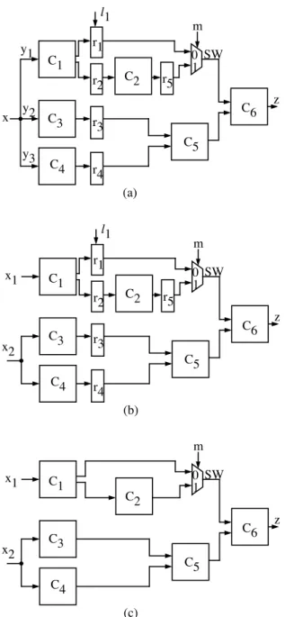
Note that we can uniquely obtain the smallest partition for each primary input. In this way, for a given acyclic cir- cuit , the resulting circuit from the separation of primary inputs and the resulting circuit from the -transformation are uniquely determined. Let and denote these circuits, respectively. Figure1 shows an RTL circuits ,
and , where are clouds, is a
switch, is a hold register and and are load reg- isters. Among three fanout branches of , pairs ( ) and ( ) are separable, and is separated into two primary inputs and in . These are also exam- ples of circuits with internally switched balanced structure (ISB-structure) and with switched balanced structure (SB- structure) mentioned later.
Now we consider a class of sequential circuits with com- binational test generation complexity. Let denote the complexity of the test generation problem for a class of circuits, where is a size of a given circuit. Let denote the class of all combinational circuits. Though it has been known that the test generation problem for class is - complete[2], the complexity for practically encountered in- stances of the problem was claimed to be only [11]. If the test generation problem for a class of sequential circuits can be reduced to one for class by some trans- formation to combinational circuits such that the complex- ity of the transformation is and it preserves the size of a circuit, then we can say that the class of sequential circuits has combinational test generation complexity. Ac- tually, the complexity of the above extended combinational transformation is and it preserves the size of a given circuit. Therefore, if the test generation problem for a class can be reduced to one for class by the extended combi- national transformation, the class has combinational test generation complexity.
To define a new structure called switched balanced struc- ture(ISB-structure), we use a topology graph of an RTL circuit and switched balanced structure (SB-structure)[5]. A topology graph of an RTL circuit is a directed graph where a set of nodes consists of clouds, switches, primary inputs and primary outputs, and a set
x y2
SW 10 y1
y3
(a) C2
C3
C4
C5
C6 r1
r2
r3
r4
r5 C1
l1 m
z
x2
SW 10 x1
(b) C2
C3
C4
C5
C6 r1
r2
r3
r4
r5 C1
l1 m
z
x2
SW 1 x1 0
(c) C2
C3
C4
C5
C6 C1
m
z
Figure 1. Example of RTL circuits: (a) (ISB- structure), (b) (SB-structure), (c) .
of arcs shows the relation between nodes connected directly or through registers or fanout points. Let denote a set of switches. A set of arcs are partitioned into three sets of hold registers, of load registers, and of connections without registers. Figures 1(a) and (b) are examples of circuits with ISB-structure and SB-structure, respectively.
Definition 2 (Switched Balanced Structure[6]) An RTL
circuit with topology graph is said to be a switched balanced structure if
1. is acyclic,
2. For any pair of , all directed paths from to are of equal depth(the number register arcs) or pass
through the same switch node , and
3. For any pair of , if any directed path from to passes through a hold register , then all such paths pass through or all pass through the same
switch node , .
Definition 3 (Internally Switched Balanced Structure) An acyclic circuit is regarded as an internally switched balanced structure (ISB-structure) if a circuit is SB-structure.
3 Reducibility to Combinational Test Gener-
ation Problem
We consider the reducibility of test generation problem of circuits with ISB-structure into combinational test gener- ation problem for each components of the circuits. We con- sider stuck-at faults at primary inputs and in clouds (combi- national logic parts), switches, and registers. For a circuit with an internally balanced structure, a single stuck-at fault
in corresponds to the fault in at the same position except the following two cases.
1. A single fault at a primary input in corresponds to a multiple fault at primary inputs in
if is separated into .
2. Single faults at control inputs of hold registers have no corresponding faults because these lines disappear in
. We consider this case later.
A multiple stuck-at-fault in corre-
sponds to a multiple stuck-at-fault in .
First we show a necessary condition to detect faults in a circuit with ISB-structure.
Example 1 Consider the circuits in Fig.1. We show an ex- ample that a test sequence for in is transformed into a test pattern for in . Assume is in and
a test sequence prop-
agates an error to a primary output at time 3 in . All the paths from to in have equal sequential depth 1, and hence the value of at time 2 affects to the value of
at time 3 via and . Therefore, we assign 1 to in . Paths from to have different sequential depths. However, a switch selects an input from a hold register
, and therefore, we assign the value of at time 3 to in . We trace the path with . Since the output value of at time 3 is loaded at time 1, we assign the value of at time 1 to in . We can find
can obtain the same output of as at time 3.
Lemma 1 Let S be a circuit with ISB-structure. If a fault at primary inputs, at data inputs/outputs of registers and switches, and in clouds in is detectable, the correspond- ing in is detectable.
Proof sketch:We show that a test sequence for in can be transformed into a test pattern for in .
Assume that propagates an error in to some primary output at time . We trace the from and find when the values affecting the value of at are applied to each of primary inputs and control inputs. If an unique time is obtained for in , we can assign the corresponding value in to the value of in .
Because is SB-structure, reconvergent paths in without switch at the reconvergent point have no hold reg- ister, and their sequential depths are equal. Starting from , we find when the values affecting the value of at are applied to each line as follows. For each cloud, the output value is affected by its input values at the same time. For each switch, the output value is affected by the control value at the same time and the selected input value at that time, since we do not consider faults in switches here and hence it is enough to consider the selected input. For each load register, the output value is affected by its input value at 1 clock cycle before. For each hold register, the output value is affected by its input value loaded lastly. If we encounter a reconvergent point of some paths such that the convergent point is not a switch, we should trace all the paths. In this case, these paths has no hold register and their sequential depths are equal. Therefore, we can find an unique time when the value of their fanout point affects the output value of the reconvergent point. From the above rules, we can find an unique time for each of primary inputs and control inputs in .
Next, we show an sufficient condition to detect faults in a circuit with ISB-structure.
Example 2 We again consider Fig.1, and show an exam- ple that a test pattern for in is transformed into a test sequence for in . Assume is in and
a test pattern propa-
gates an error to a primary output . The primary input in are separated into two primary inputs and in
. Therefore, we should apply the values of and at different times in . The sequential depth from to is fixed in since there is no hold registers between them. Though there are paths with different sequential depths from
, they reconverge at a switch and only the value from
is used. In this case, we can adjust the hold register to hold values for some clock cycles so that the values of and are applied to at different times in . We can find that a test sequence
for can obtain the same output of at time 3 as . Lemma 2 Let S be a circuit with ISB-structure. If a fault
at primary inputs, at data inputs/outputs of registers, and in clouds and switches in is detectable, the cor- responding in is detectable.
Proof sketch: We show that a test pattern for in can be transformed into a test sequence for in . Assume that propagates an error to a primary out- put . For each of control inputs and primary inputs that are not separated in , we can assign the value of in to the value of all through the . We consider the case where a primary input in in separated into primary in- puts in . If there is no hold registers from a primary input to , all the paths from to have the equal sequential depths, and hence the time when the value for is applied to can be determined. Since paths from the separable primary inputs has distinct sequential depths, there are no conflict among these primary inputs. If some path from to has a hold register, only this path is se- lected by switches or the path is not selected. If the path is selected, we can adjust the hold register by holding values for any clock cycles so that the value for can be applied to at different time from other separated primary inputs.
Lemmas 1 and 2 imply the following theorem.
Theorem 3 A class of sequential circuits with ISB- structure has combinational test generation complexity for faults at primary inputs, at data input/outputs of registers and switches, and in clouds.
Among faults mentioned in Theorem3, only single faults at primary inputs correspond to multiple faults if the pri- mary inputs are separated. However, our previous work[12] showed that the test generation problem for a multiple fault at some of primary inputs in a combinational circuit can be reduced to the test generation problem for single faults at these primary inputs. Therefore, the test generation prob- lem for single faults mentioned in Theorem3 can be reduced into the test generation problem for single faults in combi- national circuits.
Now we consider the other components. For switches, Lemma2 shows a sufficient condition to detect faults in switches, and Lemma1 shows that this condition is also a necessary condition to detect faults at data inputs/outputs of switches. Therefore, we obtained a necessary and sufficient condition to detect faults at data inputs/outputs of switches, and hence for faults equivalent to these faults. However, there are some negative cases for identification of unde- tectable faults in as follows.
x1x2
r f m1 z
m2 M
(a)
x1x2
f m1 z
m2 M
(b)
Figure 2. Faults in a switch:(a) , (b) .
Theorem 4 Let S be a circuit with ISB-structure. Even if some fault in switches is undetectable in , this does not always imply the corresponding fault is unde- tectable in .
Proof: We show a counter-example. Figure2 shows a cir- cuit with ISB-structure. To detect a stuck-at fault at control input of a multiplexor , different values are needed for both inputs of . However, we cannot justify the different values at both inputs in while we can justify such values in .
For control inputs of hold registers, we show a sufficient condition to detect the faults.
Theorem 5 Let be a hold register in a circuit with ISB- structure, and let be a line with some bit width replaced with in . If both stuck-at- and stuck-at- faults are detectable for some bit in , faults at a LOAD ENABLE control input of are detectable in .
Proof sketch:Faults at in correspond to faults at the corresponding bits and in the input and the output of in . There are test sequences and for stuck- at- fault and stuck-at- fault at in , respectively. The sequences and are also a test sequence for stuck-at- fault and stuck-at- fault at , respectively.
1. Stuck-at- fault at
The hold register always operates in HOLD mode, and therefore, the value of is always its initial value. This can be considered stuck-at faults at the output of
. Therefore, we can detect the faults by and . 2. Stuck-at- fault at
First, we apply . A test sequence can activates a stuck-at- fault at and loads the error in at some time and holds the error for ( ) clock cycles in . The error is propagated at at time . The value at at time should be to activate a stuck-at- fault. When considering the stuck-at- fault at , if the value at at time is , an error appears at at time . can propagates this error to some primary output.
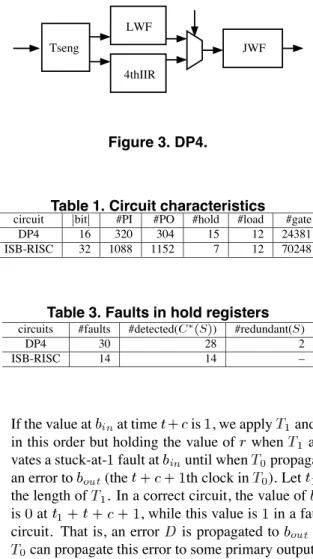
Tseng
4thIIR LWF
JWF
Figure 3. DP4.
Table 1. Circuit characteristics
circuit bit #PI #PO #hold #load #gate
DP4 16 320 304 15 12 24381
ISB-RISC 32 1088 1152 7 12 70248
Table 3. Faults in hold registers
circuits #faults #detected( ) #redundant( )
DP4 30 28 2
ISB-RISC 14 14 –
If the value at at time is , we apply and in this order but holding the value of when acti- vates a stuck-at- fault at until when propagates an error to (the th clock in ). Let be the length of . In a correct circuit, the value of is at , while this value is in a faulty circuit. That is, an error is propagated to and
can propagate this error to some primary output.
4 Experiments
We made experiments to evaluate (1)the effectiveness of using combinational ATPG to generate tests for cir- cuits with ISB-structure, and (2)fault coverage for faults in switches and registers where we only show sufficient condi- tions to detect faults. We used two circuits and - where is obtained by connecting 4 benchmark circuits Tseng, 4thIIR, LWF and JWF like Fig.3, and - is obtained from a RISC circuit. We replaced some s with scan s to make them ISB-structure. Table 1 shows the characteristics of these circuits. The columns bit , #PI, #PO, #hold, #load and #gate show the bit width, the numbers of primary inputs, primary outputs, hold regis- ters, load registers and gates, respectively. We used TestGen (Synopsys) as both combinational and sequential ATPG on Sun Blade 1000.
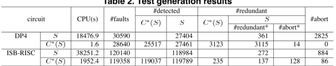
Table 2 shows the results on test generation for se- quential circuits using sequential ATPG and for com- binational circuits using combinational ATPG. We show the test generation time (CPU), the numbers of faults
Table 2. Test generation results
#detected #redundant
circuit CPU(s) #faults #abort
#redundant* #abort*
DP4 18476.9 30590 27404 361 2825
1.6 28640 25517 27461 3123 3115 14 0
ISB-RISC 38251.2 120140 118984 272 884
1952.4 119358 119037 119789 235 137 128 86
Table 4. Faults in switches
circuits #faults #detected #redundant #abort
DP4 9214 9178 36 0
9214 9178 36 0
ISB-RISC 38976 38756 207 13
38976 38756 220 0
(#fault), detected faults(#detected), identified redundant faults(#redundant), and aborted faults (#abort). For , we also show the numbers of faults in obtained from the results on . In this case, #redundant* means the number of redundant faults identified by Lemma1 and their equivalent faults, and #abort* means the number of faults that we cannot identify to be detectable or not by Lemma1 or Lemma2. We obtained higher fault coverage and fault ef-
ficiency for both and - using with
smaller test generation time than when we apply sequential ATPG to .
Table 3 shows the results on faults at control inputs of hold registers. The columns #faults, #detected( ),
#redundant( ) denote the number of faults, the number of detected faults from the results on by Theorem5, and the number of redundant faults identified in . In these two cases, test sequences are generated for all detectable faults by test generation using . Table 4 shows the results on faults in switches. We counted detectable faults in by Lemma 2 and identified redundant faults in by Lemma 1 for data inputs/outputs and their equivalent faults. We found that all the faults in switches are identified to be detectable or not by test generation using while se- quential ATPG aborted to generate test for some faults in
for - .
5 Conclusion
We proposed a new structure internally switched bal- anced structure (ISB-structure) as structure of sequen- tial circuits with combinational test generation complex- ity. The proposed structure properly includes balanced structure, internally balanced structure, switched balanced structureproposed previously. As a result, we can gener- ate tests efficiently using combinational ATPG for larger
class of sequential circuits. Moreover, we consider the faults in switches and hold registers where we treat them as macros, while other related works ignored faults inside these macros. Experimental results showed that we can gen- erate tests more efficiently using the transformed combina- tional circuits than using the original sequential circuits.
In this work, we assumed that control signals to switches and hold registers are derived from the outside of the cir- cuits. One of future works to consider circuits where such control signals are generated inside the circuits.
References
[1] M. Abramovici, M. A. Breuer, and A. D. Friedman, Digital Systems Testing and Testable Design. IEEE Press, 1990.
[2] H. Fujiwara, Logic Testing and Design for Testability. The MIT Press, 1985.
[3] A. Balakrishnan and S. T. Chakradhar, “Sequential circuits with com- binational test generation complexity,” in Proc. Intl. Conf. on VLSI Design, pp. 111–117, Jan. 1996.
[4] H. Fujiwara, “A new class of sequential circuits with combinational test generation complexity,” IEEE Trans. on Computers, vol. 49, pp. 895–905, Sept. 2000.
[5] R. Gupta and M. A. Breuer, “Partial scan design of register-tranfer level circuits,” Journal of Electronic Testing: Theory and Applica- tions, vol. 7, pp. 25–46, 1995.
[6] R. Gupta, R. Gupta, and M. Breuer, “The BALLAST methodol- ogy for structured partial scan design,” IEEE Trans. on Computers, vol. C-39, pp. 538–544, April 1990.
[7] T. Inoue, T. Hosokawa, T. Motohara, and H. Fujiwara, “An optimal time expansion model based on combinational ATPG for RT level circuits,” in Proc. Asian Test Symposium, pp. 190–197, Dec. 1998. [8] A. Kunzmann and H. Wunderich, “An analytical approach to the par-
tial scan problem,” Journal of Electronic Testing: Theory and Appli- cations, vol. 1, pp. 163–174, 1990.
[9] Y. C. Kim, V. D. Agrawal, and K. K. Saluja, “Combinational Test Generation for Acyclic Sequential Circuits using a Balanced ATPG Model,” in Proceedings of the 14th Int. Conf. on VLSI Design, pp. 143–148, Jan. 2001.
[10] Y. C. Kim, V. D. Agrawal, and K. K. Saluja, “Combinational Test Generation for Various Clases of Acyclic Sequential Circuits,” in Proc. Int. Test Conf., Oct. 2001.
[11] T. Williams and K. Parker, “Testing logic networks and designing for testability,” Computers, pp. 9–21, Oct. 1979.
[12] M. Inoue, E. Gizdarski, and H. Fujiwara, “Sequential circuits with combinational test generation complexity under single-fault assump- tion,” Journal of Electronic Testing: Theory and Applications, vol. 18, pp. 55–62, 2002.