[Issue No.]
GOT-A-0062-A
[Page]
1/63
[Title]
Precautions when Replacing GOT-A900 Series with GOT2000 Series
[Date of Issue]
January 2015
[Relevant Models]
GOT-A900 Series
→
GOT2000 Series (GT27 Models and GT25 Models)
TECHNICAL BULLETIN
Thank you for your continued support of Mitsubishi Graphic Operation Terminal (GOT).
We released the GOT2000 series with high functions and performance as an alternative of the GOT-A900 series
in September 2013. We highly recommend that you replace the GOT-A900 series with the GOT2000 series for
using new sophisticated features.
Table of Contents
1. Requests for customers ... 2
2. Replacement models ... 2
2.1 GOT ... 2
2.2 Communication ... 7
2.2.1 A bus connection ... 7
2.3 Communication unit ... 17
2.3.1 Units that require new setting method ... 18
2.3.2 Communication units and options without replaceable models ... 18
2.3.3 Precautions for replacement of communication units ... 19
2.4 Option unit ... 19
2.4.1 Precautions for replacement of option units ... 20
2.5 Option... 20
2.6 Cable ... 21
2.6.1 Q bus connection cable... 21
2.6.2 RS-232 cable ... 22
2.6.3 RS-422 cable ... 22
2.6.4 Network cable (Ethernet, MELSECNET/10, and CC-Link) ... 23
2.6.5 Other cables ... 23
2.7 Software ... 23
2.8 License ... 24
3. Comparison in specifications ... 24
3.1 Hardware specifications ... 24
3.1.1 Comparison in hardware specifications ... 24
3.1.2 Installing the GOT ... 28
3.1.3 Memory card insertion direction ... 41
3.1.4 Comparison in utility specifications ... 41
3.1.5 Precautions for hardware replacement ... 42
3.1.6 Precautions for arrangement of a 2-point press switch ... 43
3.2 Function specifications ... 46
3.2.1 Comparison in functions... 46
3.2.2 Detailed comparison in functions ... 47
3.3 Screen design software specifications ... 58
3.3.1 Preparation before converting the project data ... 58
3.3.2 Procedure for the project data conversion ... 58
3.3.3 Screen design functions that are not supported ... 60
3.3.4 Other major changes ... 60
[Issue No.]
GOT-A-0062-A
[Page]
2/63
[Title]
Precautions when Replacing GOT-A900 Series with GOT2000 Series
[Date of Issue]
January 2015
[Relevant Models]
GOT-A900 Series
→
GOT2000 Series (GT27 Models and GT25 Models)
TECHNICAL BULLETIN
1. Requests for customers
We released the GOT2000 series with high functions and performance as an alternative of the GOT-A900
series in September 2013. We highly recommend that you replace the GOT-A900 series with the GOT2000
series for using new sophisticated features.
For the replacement models, refer to "Table 2-1 Recommended replacement GOT models of the GOT2000
series" in Chapter 2 below.
2. Replacement models
"Table 2-1 Recommended replacement GOT models of the GOT2000 series" introduces recommended
models that have no or less restrictions in terms of the specifications on their replacement with the GOT2000
series. Other models can be selected depending on the usage status in your system. Select an appropriate
model after carefully considering the range of performance in the current system.
For the precautions on the replacement, refer to each chapter and section.
2.1 GOT
When you replace the GOT-A900 series with the GOT2000 series, some GOTs require the change of the panel
cutting dimensions. If you have difficulty to change the panel cutting dimensions, use the attachment.
When you use the GOT2000 series, the drawing software differs.
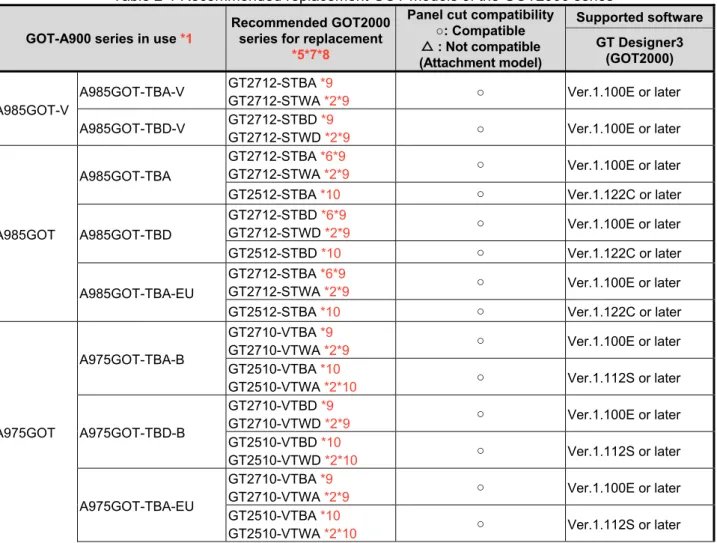
Table 2-1 Recommended replacement GOT models of the GOT2000 series
GOT-A900 series in use *1
Recommended GOT2000 series for replacement
*5*7*8
Panel cut compatibility ○: Compatible △ : Not compatible (Attachment model)
Supported software
GT Designer3 (GOT2000)
A985GOT-V
A985GOT-TBA-V GT2712-STBA *9
GT2712-STWA *2*9 ○ Ver.1.100E or later
A985GOT-TBD-V GT2712-STBD *9
GT2712-STWD *2*9 ○ Ver.1.100E or later
A985GOT
A985GOT-TBA
GT2712-STBA *6*9
GT2712-STWA *2*9 ○ Ver.1.100E or later
GT2512-STBA *10 ○ Ver.1.122C or later
A985GOT-TBD
GT2712-STBD *6*9
GT2712-STWD *2*9 ○ Ver.1.100E or later
GT2512-STBD *10 ○ Ver.1.122C or later
A985GOT-TBA-EU
GT2712-STBA *6*9
GT2712-STWA *2*9 ○ Ver.1.100E or later
GT2512-STBA *10 ○ Ver.1.122C or later
A975GOT
A975GOT-TBA-B
GT2710-VTBA *9
GT2710-VTWA *2*9 ○ Ver.1.100E or later
GT2510-VTBA *10
GT2510-VTWA *2*10 ○ Ver.1.112S or later
A975GOT-TBD-B
GT2710-VTBD *9
GT2710-VTWD *2*9 ○ Ver.1.100E or later
GT2510-VTBD *10
GT2510-VTWD *2*10 ○ Ver.1.112S or later
A975GOT-TBA-EU
GT2710-VTBA *9
GT2710-VTWA *2*9 ○ Ver.1.100E or later
GT2510-VTBA *10
[Issue No.]
GOT-A-0062-A
[Page]
3/63
[Title]
Precautions when Replacing GOT-A900 Series with GOT2000 Series
[Date of Issue]
January 2015
[Relevant Models]
GOT-A900 Series
→
GOT2000 Series (GT27 Models and GT25 Models)
TECHNICAL BULLETIN
GOT-A900 series in use *1
Recommended GOT2000 series for replacement
*5*7*8
Panel cut compatibility ○: Compatible △ : Not compatible (Attachment model)
Supported software
GT Designer3 (GOT2000)
A975GOT
A975GOT-TBA
GT2710-VTBA *9
GT2710-VTWA *2*9 ○ Ver.1.100E or later
GT2510-VTBA *10
GT2510-VTWA *2*10 ○ Ver.1.112S or later
A975GOT-TBD
GT2710-VTBD *9
GT2710-VTWD *2*9 ○ Ver.1.100E or later
GT2510-VTBD *10
GT2510-VTWD *2*10 ○ Ver.1.112S or later
A970GOT
A970GOT-TBA-B
GT2710-VTBA *9
GT2710-VTWA *2*9 ○ Ver.1.100E or later
GT2510-VTBA *10
GT2510-VTWA *2*10 ○ Ver.1.112S or later
A970GOT-TBD-B
GT2710-VTBD *9
GT2710-VTWD *2*9 ○ Ver.1.100E or later
GT2510-VTBD *10
GT2510-VTWD *2*10 ○ Ver.1.112S or later
A970GOT-TBA-EU
GT2710-VTBA *9
GT2710-VTWA *2*9 ○ Ver.1.100E or later
GT2510-VTBA *10
GT2510-VTWA *2*10 ○ Ver.1.112S or later
A970GOT-TBA
GT2710-VTBA *9
GT2710-VTWA *2*9 ○ Ver.1.100E or later
GT2510-VTBA *10
GT2510-VTWA *2*10 ○ Ver.1.112S or later
A970GOT-TBD
GT2710-VTBD *9
GT2710-VTWD *2*9 ○ Ver.1.100E or later
GT2510-VTBD *10
GT2510-VTWD *2*10 ○ Ver.1.112S or later
A970GOT-SBA
GT2710-VTBA *3*9
GT2710-VTWA *2*3*9 ○ Ver.1.100E or later
GT2510-VTBA *3
GT2510-VTWA *2*3 ○ Ver.1.112S or later
A970GOT-SBD
GT2710-VTBD *3*9
GT2710-VTWD *2*3*9 ○ Ver.1.100E or later
GT2510-VTBD *3
GT2510-VTWD *2*3 ○ Ver.1.112S or later
A970GOT-SBA-EU
GT2710-VTBA *3*9
GT2710-VTWA *2*3*9 ○ Ver.1.100E or later
GT2510-VTBA *3
GT2510-VTWA *2*3 ○ Ver.1.112S or later
A970GOT-LBA
GT2710-VTBA *3*9
GT2710-VTWA *2*3*9 ○ Ver.1.100E or later
GT2510-VTBA *3*10
GT2510-VTWA *2*3*10 ○ Ver.1.112S or later
[Issue No.]
GOT-A-0062-A
[Page]
4/63
[Title]
Precautions when Replacing GOT-A900 Series with GOT2000 Series
[Date of Issue]
January 2015
[Relevant Models]
GOT-A900 Series
→
GOT2000 Series (GT27 Models and GT25 Models)
TECHNICAL BULLETIN
GOT-A900 series in use *1
Recommended GOT2000 series for replacement
*5*7*8
Panel cut compatibility ○: Compatible △ : Not compatible (Attachment model)
Supported software
GT Designer3 (GOT2000)
A970GOT
A970GOT-LBA GT2508-VTBA *3*10
GT2508-VTWA *2*3*10 △(GT15-60ATT-97) Ver.1.112S or later
A970GOT-LBD
GT2710-VTBD *3*9
GT2710-VTWD *2*3*9 ○ Ver.1.100E or later
GT2510-VTBD *3*10
GT2510-VTWD *2*3*10 ○ Ver.1.112S or later
GT2708-VTBD *3*9 △(GT15-60ATT-97) Ver.1.100E or later
GT2508-VTBD *3*10
GT2508-VTWD *2*3*10 △(GT15-60ATT-97) Ver.1.112S or later
A970GOT-LBA-EU
GT2710-VTBA *3*9
GT2710-VTWA *2*3*9 ○ Ver.1.100E or later
GT2510-VTBA *3*10
GT2510-VTWA *2*3*10 ○ Ver.1.112S or later
GT2708-VTBA *3*9 △(GT15-60ATT-97) Ver.1.100E or later
GT2508-VTBA *3*10
GT2508-VTWA *2*3*10 △(GT15-60ATT-97) Ver.1.112S or later
A960GOT
A960GOT-EBA
GT2708-VTBA *3*9*11 △(GT15-60ATT-96) Ver.1.100E or later
GT2508-VTBA *3*10*11
GT2508-VTWA *2*3*10*11 △(GT15-60ATT-96) Ver.1.112S or later
A960GOT-EBD
GT2708-VTBD *3*9*11 △(GT15-60ATT-96) Ver.1.100E or later
GT2508-VTBD *3*10*11
GT2508-VTWD *2*3*10*11 △(GT15-60ATT-96) Ver.1.112S or later
A960GOT-EBA-EU
GT2708-VTBA *3*9*11 △(GT15-60ATT-96) Ver.1.100E or later
GT2508-VTBA *3*10*11
GT2508-VTWA *2*3*10*11 △(GT15-60ATT-96) Ver.1.112S or later
A956WGOT A956WGOT-TBD - *4 - -
A956GOT
A956GOT-TBD-M3 - *4 - -
A956GOT-TBD - *4 - -
A956GOT-SBD-M3-B - *4 - -
A956GOT-SBD-B - *4 - -
A956GOT-SBD-M3 - *4 - -
A956GOT-SBD - *4 - -
A956GOT-LBD-M3 - *4 - -
A956GOT-LBD - *4 - -
A953GOT
A953GOT-TBD-M3 - *4 - -
A953GOT-TBD - *4 - -
A953GOT-SBD-M3-B - *4 - -
A953GOT-SBD-B - *4 - -
A953GOT-SBD-M3 - *4 - -
A953GOT-SBD - *4 - -
A953GOT-LBD-M3 - *4 - -
[Issue No.]
GOT-A-0062-A
[Page]
5/63
[Title]
Precautions when Replacing GOT-A900 Series with GOT2000 Series
[Date of Issue]
January 2015
[Relevant Models]
GOT-A900 Series
→
GOT2000 Series (GT27 Models and GT25 Models)
TECHNICAL BULLETIN
GOT-A900 series in use *1
Recommended GOT2000 series for replacement
*5*7*8
Panel cut compatibility ○: Compatible △ : Not compatible (Attachment model)
Supported software
GT Designer3 (GOT2000)
A951GOT
A951GOT-QTBD-M3 - *4 - -
A951GOT-QTBD - *4 - -
A951GOT-QSBD-M3-B - *4 - -
A951GOT-QSBD-B - *4 - -
A951GOT-QSBD-M3 - *4 - -
A951GOT-QSBD - *4 - -
A951GOT-QLBD-M3 - *4 - -
A951GOT-QLBD - *4 - -
A951GOT-TBD-M3 - *4 - -
A951GOT-TBD - *4 - -
A951GOT-SBD-M3-B - *4 - -
A951GOT-SBD-B - *4 - -
A951GOT-SBD-M3 - *4 - -
A951GOT-SBD - *4 - -
A951GOT-LBD-M3 - *4 - -
A951GOT-LBD - *4 - -
A950GOT
A950GOT-TBD-M3 - *4 - -
A950GOT-TBD - *4 - -
A950GOT-SBD-M3-B - *4 - -
A950GOT-SBD-B - *4 - -
A950GOT-SBD-M3 - *4 - -
A950GOT-SBD - *4 - -
A950GOT-LBD-M3 - *4 - -
A950GOT-LBD - *4 - -
*1 Production of all the GOT-A900 series models was discontinued.
*2 This model has a white front panel. For the difference in the specifications between the white-panel model and standard model (black panel), refer to Section 3.1.1 (3).
*3 The display color is replaced with 65536 colors since the GOT2000 series does not support 256, 16, 8, 2 (black/yellow orange), and 2 (monochrome) colors. Note that the price range differs. For the details, refer to the GOT2000 series catalog (L(NA)08274ENG).
*4 No models for replacement are prepared.
*5 The Sound output function is an option for the GOT2000 series. When using the sound output function of the GOT-A900 series, use the sound output unit (GT15-SOUT) of the GOT2000 series separately.
*6 The RGB output function is an option for the GOT2000 series. When using the RGB output function of the GOT-A900 series, use the RGB output unit (GT27-ROUT-Z) of the GOT2000 series separately.
*7 To use the printer function with the GOT2000 series, two methods are provided. When using a serial printer, use the built-in RS-232 interface.
When using a PictBridge-compatible printer, prepare the printer unit (GT15-PRN). *8 The GOT2000 series has no RUN/OUTPUT terminal in the power supply section.
When using the RUN/OUTPUT terminal in the power supply section of the GOT-A900 series, consider using the RUN output of the external I/O unit (GT15-DIO or GT15-DIOR). For the details of the external I/O unit, refer to the following.
[Issue No.]
GOT-A-0062-A
[Page]
6/63
[Title]
Precautions when Replacing GOT-A900 Series with GOT2000 Series
[Date of Issue]
January 2015
[Relevant Models]
GOT-A900 Series
→
GOT2000 Series (GT27 Models and GT25 Models)
TECHNICAL BULLETIN
*9 The display section of the GT27 is an analog-resistive type touch panel that accepts 2-point press. However, note that there are precautions on the arrangement of 2-point press switches. For the details, refer to Section 3.1.6. *10 The display section of the GT25 is an analog-resistive type touch panel. When you touch two points or more
simultaneously on the display section, any touch switch located around the center of the touched points may operate. Do not touch two or more points on the display section simultaneously.
[Issue No.]
GOT-A-0062-A
[Page]
7/63
[Title]
Precautions when Replacing GOT-A900 Series with GOT2000 Series
[Date of Issue]
January 2015
[Relevant Models]
GOT-A900 Series
→
GOT2000 Series (GT27 Models and GT25 Models)
TECHNICAL BULLETIN
2.2 Communication
2.2.1 A bus connection
No further orders for all the models of the A bus connection unit will be accepted in and after January 2015, and
the production will be discontinued in and after February 2015. When the GOT-A900 series is connected by the
A bus connection, the connection type must be changed or the PLC must be replaced.
To replace the PLC, refer to the following Technical Bulletin.
➟
Production discontinuation of MELSEC-AnS/QnAS (small type) series and MELSEC-I/OLINK
(FA-A-0142)
Production discontinuation of MELSEC-A/QnA (large type) series (T99-0050)
To change the A bus connection to another connection type, refer
to the following.
➟
■
1. Settings of the GOT and PLC
■
2. Connection type
■
1. Settings of the GOT and PLC
When changing the connection type, check the settings of the PLC and GOT.
(1) PLC
When the GOT connected by the bus connection is removed or a communication unit is added to the PLC, the
PLC may require new settings. According to the PLC configuration, check the parameter setting (including I/O
assignment) and I/O numbers in the sequence program.
(2) GOT
Change the controller setting. *1
When changing the connection type to the network connection (excluding the Ethernet connection), set the
network number and station number in the device number of each object. *2
*1 Example of the controller setting
[Issue No.]
GOT-A-0062-A
[Page]
8/63
[Title]
Precautions when Replacing GOT-A900 Series with GOT2000 Series
[Date of Issue]
January 2015
[Relevant Models]
GOT-A900 Series
→
GOT2000 Series (GT27 Models and GT25 Models)
TECHNICAL BULLETIN
*2 Setting of the network number and station number
To monitor D0 of the CPU in the network number 1 and station number 2
■
2. Connection type
(1) Changing the connection type to the serial connection
(a) Direct Connection to CPU
Connect the GOT in the following configuration.
PLC GOT
Connection cable
1) When connecting the GOT with MELSEC-A (ACPU, AnCPU, AnSCPU) or MELSEC-QnA (QnACPU,
QnASCPU)
PLC
Cable model *1
GOT
Model name Communication
type Option device Model
MELSEC-A(ACPU) MELSEC-A(AnCPU) MELSEC-A(AnSCPU) MELSEC-Q(QnACPU) MELSEC-Q(QnASCPU)
RS-422 GT01-C30R4-25P(3m) GT01-C100R4-25P(10m)
GT01-C200R4-25P(20m) GT01-C300R4-25P(30m)
GT15-RS4-9S GT27, GT25
(Built into GOT)
[Issue No.]
GOT-A-0062-A
[Page]
9/63
[Title]
Precautions when Replacing GOT-A900 Series with GOT2000 Series
[Date of Issue]
January 2015
[Relevant Models]
GOT-A900 Series
→
GOT2000 Series (GT27 Models and GT25 Models)
TECHNICAL BULLETIN
(b) Computer Link Connection
Connect the GOT in the following configuration.
Changing the connection type to the computer link connection requires a computer link module on the PLC
side.
Computer link module
PLC GOT
Connection cable
1) When connecting the GOT with MELSEC-A (ACPU, AnCPU)
PLC
Cable model
*1*2
GOT
Computer link
module
Communication
type
Option device
Model
AJ71UC24 *3 RS-232
GT09-C30R2-25P(3m)
Cables prepared by the user
(max.: 15m)
(Built into GOT)
GT27, GT25
GT15-RS2-9P
RS-422 GT09-C30R4-6C(3m)
GT09-C100R4-6C(10m)
GT09-C200R4-6C(20m)
GT09-C300R4-6C(30m)
Cables prepared by the user
(max.: 500m)
(Built into GOT)
GT27, GT25
GT15-RS4-9S
*1 For cables prepared by the user, refer to the following.
➟
GOT2000 Series Connection Manual (Mitsubishi Products) For GT Works3 Version1
*2 If the connection distance exceeds 30m, consider changing the connection type to the connection
using a cable prepared by the user or the network connection.
*3 Production of this module has been discontinued.
2) When connecting the GOT with MELSEC-A (AnSCPU, A0J2HCPU, A2CCPU)
PLC
Cable model
*1*2
GOT
Computer link
module
Communication
type
Option device
Model
A1SJ71UC24-R2 *3
A1SJ71C24-R2 *3
A1SJ71UC24-PRF
*3
A1SJ71C24-PRF *3
RS-232 GT09-C30R2-29P(3m)
Cables prepared by the user
(max.: 15m)
(Built into GOT)
GT27, GT25
GT15-RS2-9P
A1SJ71UC24-R4 *3
A1SJ71C24-R4 *3
RS-422 GT09-C30R4-6C(3m)
GT09-C100R4-6C(10m)
GT09-C200R4-6C(20m)
GT09-C300R4-6C(30m)
Cables prepared by the user
(max.: 500m)
(Built into GOT)
GT27, GT25
GT15-RS4-9S
*1 For cables prepared by the user, refer to the following.
➟
GOT2000 Series Connection Manual (Mitsubishi Products) For GT Works3 Version1
*2 If the connection distance exceeds 30m, consider changing the connection type to the connection
using a cable prepared by the user or the network connection.
[Issue No.]
GOT-A-0062-A
[Page]
10/63
[Title]
Precautions when Replacing GOT-A900 Series with GOT2000 Series
[Date of Issue]
January 2015
[Relevant Models]
GOT-A900 Series
→
GOT2000 Series (GT27 Models and GT25 Models)
TECHNICAL BULLETIN
3) When connecting the GOT with MELSEC-QnA (QnACPU)
PLC
Cable model
*1*2
GOT
Serial communication /Computer link module
Communication
type
Option device
Model
AJ71QC24 *4
AJ71QC24N *4
AJ71QC24-R2 *4
AJ71QC24N-R2 *4
RS-232 GT09-C30R2-25P(3m)
Cables prepared by the user
(max.: 15m)
(Built into GOT)
GT27, GT25
GT15-RS2-9P
AJ71QC24-R4 *4
AJ71QC24N-R4 *4
RS-422 GT01-C30R4-25P(3m)
GT01-C100R4-25P(1m)
GT01-C200R4-25P(20m)
GT01-C300R4-25P(30m)
(Built into GOT)
GT27, GT25
GT15-RS4-9S
AJ71QC24 *4
AJ71QC24N *4
AJ71QC24-R4 *4
AJ71QC24N-R4 *4
RS-422 GT09-C30R4-6C(3m)
GT09-C100R4-6C(10m)
GT09-C200R4-6C(20m)
GT09-C300R4-6C(30m)
Cables prepared by the user
(max.: 1200m)
(Built into GOT)
GT27, GT25
GT15-RS4-9S
AJ71UC24 *3*4 RS-232
GT09-C30R2-25P(3m)
Cables prepared by the user
(max.: 15m)
(Built into GOT)
GT27, GT25
GT15-RS2-9P
AJ71UC24 *3*4 RS-422
GT09-C30R4-6C(3m)
GT09-C100R4-6C(10m)
GT09-C200R4-6C(20m)
GT09-C300R4-6C(30m)
Cables prepared by the user
(max.: 500m)
(Built into GOT)
GT27, GT25
GT15-RS4-9S
*1 For cables prepared by the user, refer to the following.
➟
GOT2000 Series Connection Manual (Mitsubishi Products) For GT Works3 Version1
*2 If the connection distance exceeds 30m, consider changing the connection type to the connection
using a cable prepared by the user or the network connection.
[Issue No.]
GOT-A-0062-A
[Page]
11/63
[Title]
Precautions when Replacing GOT-A900 Series with GOT2000 Series
[Date of Issue]
January 2015
[Relevant Models]
GOT-A900 Series
→
GOT2000 Series (GT27 Models and GT25 Models)
TECHNICAL BULLETIN
4) When connecting the GOT with MELSEC-QnA (QnASCPU)
PLC
Cable model
*1*2
GOT
Serial communication /Computer link module
Communication
type
Option device
Model
A1SJ71QC24 *4
A1SJ71QC24N *4
A1SJ71QC24N1
*4
A1SJ71QC24-R2
*4
A1SJ71QC24N-R2
*4
A1SJ71QC24N1-R
2 *4
RS-232 GT09-C30R2-9P(3m)
Cables prepared by the user
(max.: 15m)
(Built into GOT)
GT27, GT25
GT15-RS2-9P
A1SJ71QC24 *4
A1SJ71QC24N *4
A1SJ71QC24N1
*4
RS-422 GT09-C30R4-6C(3m)
GT09-C100R4-6C(10m)
GT09-C200R4-6C(20m)
GT09-C300R4-6C(30m)
Cables prepared by the user
(max.: 1200m)
(Built into GOT)
GT27, GT25
GT15-RS4-9S
A1SJ71UC24-R2
*3*4
A1SJ71C24-R2
*3*4
A1SJ71UC24-PRF
*3*4
A1SJ71C24-PRF
*3*4
RS-232 GT09-C30R2-29P(3m)
Cables prepared by the user
(max.: 15m)
(Built into GOT)
GT27, GT25
GT15-RS2-9P
A1SJ71UC24-R4
*3*4
A1SJ71C24-R4
*3*4
RS-422 GT09-C30R4-6C(3m)
GT09-C100R4-6C(10m)
GT09-C200R4-6C(20m)
GT09-C300R4-6C(30m)
Cables prepared by the user
(max.: 500m)
(Built into GOT)
GT27, GT25
GT15-RS4-9S
*1 For cables prepared by the user, refer to the following.
➟
GOT2000 Series Connection Manual (Mitsubishi Products) For GT Works3 Version1
*2 If the connection distance exceeds 30m, consider changing the connection type to the connection
using a cable prepared by the user or the network connection.
[Issue No.]
GOT-A-0062-A
[Page]
12/63
[Title]
Precautions when Replacing GOT-A900 Series with GOT2000 Series
[Date of Issue]
January 2015
[Relevant Models]
GOT-A900 Series
→
GOT2000 Series (GT27 Models and GT25 Models)
TECHNICAL BULLETIN
(2) Changing the connection type to the network connection
(a) MELSECNET/10 Connection
Connect the GOT in the following configuration.
Changing the connection type to the MELSECNET/10 connection requires a MELSECNET/10 network module
on the PLC side.
The GOT side requires a MELSECNET/H communication unit (used in the MELSECNET/10 mode).
MELSECNET/10
network module GOT
Connection cable PLC
1) When connecting the GOT with MELSEC-A (AnCPU
*1
, AnSCPU
*1
) (optical loop system)
PLC
Cable model
GOT
MELSECNET/H
network module
Communication
type
Option device
Model
AJ71LP21 *3
A1SJ71LP21
MELSECNET/10
Optical fiber cable
GT15-J71LP23-25
*2
GT27, GT25
*1 The following PLCs can be connected: A2UCPU, A2UCPU-S1, A3UCPU, A4UCPU, A2USCPU,
A2USCPU-S1, and A2USHCPU-S1.
*2 Set the MELSECNET/10 mode in the controller setting.
*3 Production of this module has been discontinued.
2) When connecting the GOT with MELSEC-QnA (QnACPU, QnASCPU) (optical loop system)
PLC
Cable model
GOT
MELSECNET/H
network module
Communication
type
Option device
Model
AJ71QLP21 *2
AJ71QLP21S *2
A1SJ71QLP21
A1SJ71QLP21S *2
MELSECNET/10
Optical fiber cable
GT15-J71LP23-25
*1
GT27, GT25
*1 Set the MELSECNET/10 mode in the controller setting.
*2 Production of this module has been discontinued.
3) When connecting the GOT with MELSEC-A (AnCPU
*1
, AnSCPU
*1
) (coaxial bus system)
PLC
Cable model
GOT
MELSECNET/H
network module
Communication
type
Option device
Model
AJ71BR11 *3
A1SJ71BR11
MELSECNET/10
Optical fiber cable
GT15-J71BR13 *2
GT27, GT25
*1 The following PLCs can be connected: A2UCPU, A2UCPU-S1, A3UCPU, A4UCPU, A2USCPU,
A2USCPU-S1, and A2USHCPU-S1.
[Issue No.]
GOT-A-0062-A
[Page]
13/63
[Title]
Precautions when Replacing GOT-A900 Series with GOT2000 Series
[Date of Issue]
January 2015
[Relevant Models]
GOT-A900 Series
→
GOT2000 Series (GT27 Models and GT25 Models)
TECHNICAL BULLETIN
4) When connecting the GOT with MELSEC-QnA (QnACPU, QnASCPU) (coaxial bus system)
PLC
Cable model
GOT
MELSECNET/H
network module
Communication
type
Option device
Model
AJ71QBR11 *2
A1SJ71QBR11
MELSECNET/10
Optical fiber cable
GT15-J71BR13 *1 GT27,
GT25
*1 Set the MELSECNET/10 mode in the controller setting.
*2 Production of this module has been discontinued.
(b) CC-Link Connection (Intelligent Device Station)
Connect the GOT in the following configuration.
Changing the connection type to the CC-Link (intelligent device station) connection requires a CC-Link module
on the PLC side.
CC-Link module
PLC GOT
Connection cable
1) When connecting the GOT with MELSEC-A (ACPU
*1
, AnCPU, AnSCPU)
PLC
Cable model
GOT
CC-Link module
Communication
type
Option device
Model
AJ61BT11 *3
A1SJ61BT11
CC-Link (Ver.1)
CC-Link dedicated cable
GT15-J61BT13 *2 GT27,
GT25
*1 Only A0J2HCPU, A0J2HCPUP21, A0J2HCPUR21, and A0J2HCPU-DC24 can be connected.
*2 Specify Ver.1 as the mode setting in the Communication Settings to use it.
*3 Production of this module has been discontinued.
2) When connecting the GOT with MELSEC-QnA (QnACPU, QnASCPU)
PLC
Cable model
GOT
CC-Link module
Communication
type
Option device
Model
AJ61QBT11 *2
A1SJ61QBT11
CC-Link (Ver.1)
CC-Link dedicated cable
GT15-J61BT13 *1 GT27,
GT25
*1 Specify Ver.1 as the mode setting in the Communication Settings to use it.
[Issue No.]
GOT-A-0062-A
[Page]
14/63
[Title]
Precautions when Replacing GOT-A900 Series with GOT2000 Series
[Date of Issue]
January 2015
[Relevant Models]
GOT-A900 Series
→
GOT2000 Series (GT27 Models and GT25 Models)
TECHNICAL BULLETIN
(c) Ethernet Connection
Connect the GOT in the following configuration.
Changing the connection type to the Ethernet connection requires an Ethernet module on the PLC side.
Ethernet
module GOT
Connection cable PLC
1) When connecting the GOT with MELSEC-A (AnCPU, AnSCPU)
PLC
Cable model
GOT
Ethernet module
Communication
type
Option device
Model
AJ71E71N3-T *1
AJ71E71N-B5 *1
AJ71E71N-B2 *1
AJ71E71N-T *1
AJ71E71N-B5T *1
AJ71E71-S3 *1
A1SJ71E71N3-T *1
A1SJ71E71N-B5 *1
A1SJ71E71N-B2 *1
A1SJ71E71N-T *1
A1SJ71E71N-B5T *1
A1SJ71E71-B5-S3 *1
A1SJ71E71-B2-S3 *1
Ethernet
Twisted pair cable
・
10BASE-T
・
100BASE-TX
(Built into GOT)
GT27, GT25
[Issue No.]
GOT-A-0062-A
[Page]
15/63
[Title]
Precautions when Replacing GOT-A900 Series with GOT2000 Series
[Date of Issue]
January 2015
[Relevant Models]
GOT-A900 Series
→
GOT2000 Series (GT27 Models and GT25 Models)
TECHNICAL BULLETIN
2) When connecting the GOT with MELSEC-QnA (QnACPU, QnASCPU)
PLC
Cable model
GOT
Ethernet module
Communication
type
Option device
Model
AJ71QE71N3-T *1
AJ71QE71N-B5 *1
AJ71QE71N-B2 *1
AJ71QE71N-T *1
AJ71QE71N-B5T *1
AJ71QE71 *1
AJ71QE71-B5 *1
A1SJ71QE71N3-T *1
A1SJ71QE71N-B5 *1
A1SJ71QE71N-B2 *1
A1SJ71QE71N-T *1
A1SJ71QE71N-B5T *1
A1SJ71QE71-B5 *1
A1SJ71QE71-B2 *1
Ethernet
Twisted pair cable
・
10BASE-T
・
100BASE-TX
(Built into GOT)
GT27, GT25
*1 Production of this module has been discontinued.
(3) Changing the connection type when multiple GOTs are connected
Consider the following connection types for the configuration in which the multiple GOTs are connected.
・
Network Connection
➟
2.2.1
■
2 (2) Changing the connection type to the network connection
・
Multi-Drop Connection
➟
(a) Multi-Drop Connection
(a) Multi-Drop Connection
*1
Connect the GOT in the following configuration.
Changing the connection type to the multi-drop connection requires the following option devices and cables.
GOT GOT
PLC
Varies according to the connection type.
[Issue No.]
GOT-A-0062-A
[Page]
16/63
[Title]
Precautions when Replacing GOT-A900 Series with GOT2000 Series
[Date of Issue]
January 2015
[Relevant Models]
GOT-A900 Series
→
GOT2000 Series (GT27 Models and GT25 Models)
TECHNICAL BULLETIN
1) When connecting the GOT with MELSEC-A (ACPU, AnCPU, AnSCPU)
*1
or MELSEC-QnA (QnACPU
*2
,
QnASCPU)
For the system configuration between the serial multi-drop connection unit and PLC, refer to the items about
each connection type.
Multi-Drop Connection Unit
Cable model
*3
GOT
Serial Multi-Drop Connection Unit
Communication
type
Option device
Model
GT01-RS4-M RS-485
FA-LTBGTR4CBL05(0.5m)
FA-LTBGTR4CBL10(1m)
FA-LTBGTR4CBL20(2m)
Cables prepared by the user
(max.: 15m)
(Built into GOT)
GT27, GT25
GT15-RS4-9S
GT15-RS4-TE
*1 These PLCs cannot be connected to the serial multi-drop connection unit in the computer link
connection.
*2 Q4ARCPU cannot be connected.
*3 For cables prepared by the user, refer to the following.
[Issue No.]
GOT-A-0062-A
[Page]
17/63
[Title]
Precautions when Replacing GOT-A900 Series with GOT2000 Series
[Date of Issue]
January 2015
[Relevant Models]
GOT-A900 Series
→
GOT2000 Series (GT27 Models and GT25 Models)
TECHNICAL BULLETIN
2.3 Communication unit
Most of the communication units of the GOT2000 series can be used together with the GOT2000 series as-is.
Check the availability of use in the following table.
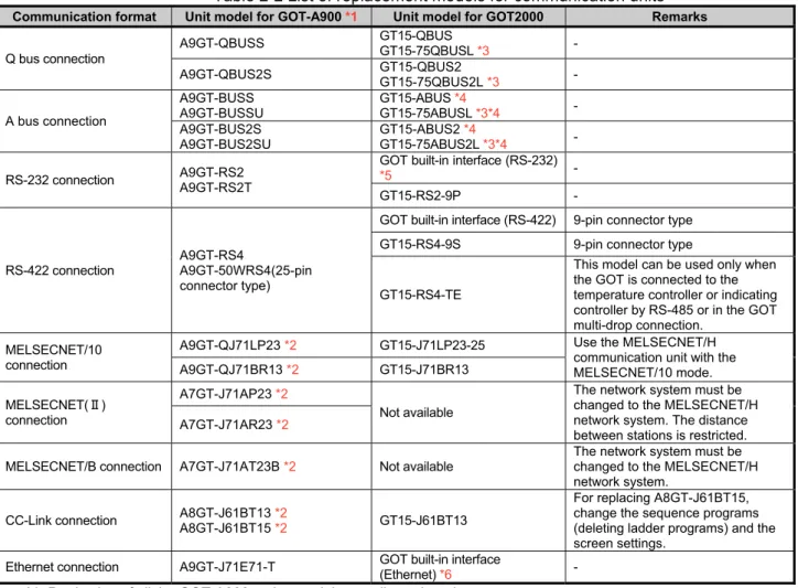
Table 2-2 List of replacement models for communication units
Communication format Unit model for GOT-A900 *1 Unit model for GOT2000 Remarks
Q bus connection
A9GT-QBUSS GT15-QBUS
GT15-75QBUSL *3 -
A9GT-QBUS2S GT15-QBUS2
GT15-75QBUS2L *3 -
A bus connection
A9GT-BUSS A9GT-BUSSU
GT15-ABUS *4
GT15-75ABUSL *3*4 -
A9GT-BUS2S A9GT-BUS2SU
GT15-ABUS2 *4
GT15-75ABUS2L *3*4 -
RS-232 connection A9GT-RS2 A9GT-RS2T
GOT built-in interface (RS-232)
*5 -
GT15-RS2-9P -
RS-422 connection
A9GT-RS4
A9GT-50WRS4(25-pin connector type)
GOT built-in interface (RS-422) 9-pin connector type
GT15-RS4-9S 9-pin connector type
GT15-RS4-TE
This model can be used only when the GOT is connected to the temperature controller or indicating controller by RS-485 or in the GOT multi-drop connection.
MELSECNET/10 connection
A9GT-QJ71LP23 *2 GT15-J71LP23-25 Use the MELSECNET/H
communication unit with the MELSECNET/10 mode.
A9GT-QJ71BR13 *2 GT15-J71BR13
MELSECNET(Ⅱ) connection
A7GT-J71AP23 *2
Not available
The network system must be changed to the MELSECNET/H network system. The distance between stations is restricted. A7GT-J71AR23 *2
MELSECNET/B connection A7GT-J71AT23B *2 Not available
The network system must be changed to the MELSECNET/H network system.
CC-Link connection A8GT-J61BT13 *2
A8GT-J61BT15 *2 GT15-J61BT13
For replacing A8GT-J61BT15, change the sequence programs (deleting ladder programs) and the screen settings.
Ethernet connection A9GT-J71E71-T GOT built-in interface
(Ethernet) *6 -
*1 Production of all the GOT-A900 series models was discontinued.
*2 The GOT-A900 series communication unit has setting switches, including rotary switches. Though the GOT2000 series communication unit does not have rotary switches and others, setting switches is required with software. Therefore, set the switches with the drawing software or the utility. For details, refer to Section 2.3.1.
*3 The slim model has limitation for combination with other units. To use the slim model together with the units that have the external I/O function, the sound output function, the printer function, the video/RGB I/O function, or others, use the following units.
・GT15-QBUS (Q bus connection 1ch)
・GT15-QBUS2 (Q bus connection 2ch)
・GT15-ABUS (A bus connection 1ch)
・GT15-ABUS2 (A bus connection 2ch)
*4 No further orders will be accepted in and after January 2015, and the production will be discontinued in and after February 2015.
*5 To download monitor screen data and others from a personal computer to the GOT via the GOT built-in RS-232 interface, the cable must be replaced.
[Issue No.]
GOT-A-0062-A
[Page]
18/63
[Title]
Precautions when Replacing GOT-A900 Series with GOT2000 Series
[Date of Issue]
January 2015
[Relevant Models]
GOT-A900 Series
→
GOT2000 Series (GT27 Models and GT25 Models)
TECHNICAL BULLETIN
2.3.1 Units that require new setting method
The communication units for the GOT-A900 series listed below require settings with rotary switches and others
on the hardware. However, the communication units for the GOT2000 series do not have rotary switches and
others, and settings with the drawing software or the utility are required. For GOT2000 series, refer to the
following table.
Table 2-3 Units that require new setting method and new setting method after change
GOT-A900 series communication module GOT2000 series communication unitItem Model Settings on hardware Model Setting method
CC-Link communication module
A8GT-J61BT13 A8GT-J61BT15
(1) Mode setting switch: (A8GT-J61BT13 only) Online/Offline
(2) Station number setting switch:
tens place, ones place (3) Transmission baudrate setting switch
(4) Condition setting switch: Input data status of data link faulty station (A8GT-J61BT13 only), number of occupied stations
GT15-J61BT13
Set with the drawing software (GT Designer3 (GOT2000)) or utility of the GOT.
MELSECNET/10 connection
A9GT-QJ71LP23
(1) Mode setting switch: Online/Offline
(2) Station number setting switch:
tens place, ones place (3) Transmission Group number setting switch (4) Network number setting switch:
hundreds place, tens place, ones place
GT15-J71LP23-25
Set with the drawing software (GT Designer3 (GOT2000)) or utility of the GOT.
A9GT-QJ71BR13 GT15-J71BR13
2.3.2 Communication units and options without replaceable models
The communication units and options for the GOT-A900 series listed below do not have alternative models to be
compatible with the GOT2000 series.
Consider the following alternative plans.
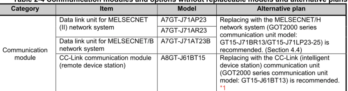
Table 2-4 Communication modules and options without replaceable models and alternative plans
Category Item Model Alternative plan
Communication module
Data link unit for MELSECNET (II) network system
A7GT-J71AP23 Replacing with the MELSECNET/H
network system (GOT2000 series communication unit model:
GT15-J71BR13/GT15-J71LP23-25) is recommended. (Section 4.4)
A7GT-J71AR23
Data link unit for MELSECNET/B network system
A7GT-J71AT23B
CC-Link communication module (remote device station)
A8GT-J61BT15 Replacing with the CC-Link (intelligent
device station) communication unit (GOT2000 series communication unit model: GT15-J61BT13) is recommended.
*1
*1 -Maximum number of connected units is reduced from 32 to 26. When connecting more than 26 units, consider adding a master station to support the system.
[Issue No.]
GOT-A-0062-A
[Page]
19/63
[Title]
Precautions when Replacing GOT-A900 Series with GOT2000 Series
[Date of Issue]
January 2015
[Relevant Models]
GOT-A900 Series
→
GOT2000 Series (GT27 Models and GT25 Models)
TECHNICAL BULLETIN
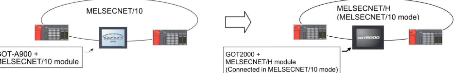
2.3.3 Precautions for replacement of communication units
(1) Replacing the GOT-A900 series connected to the MELSECNET/10 (programmable controller to
programmable controller optical loop/coaxial bus)) network system with the GOT2000 series
Use the MELSECNET/H communication unit listed in Section 2.3, set the MELSECNET/H communication unit
to the MELSECNET/10 mode, and connect the GOT to the MELSECNET/10 network system.
* For the details, refer to "GOT2000 Series Connection Manual (Mitsubishi Product) For GT Works3
Version1 (SH-081197ENG)".
Figure 2-1 Replacement example that requires a change in the network system configuration
2.4 Option unit
The GOT-A900 series option units cannot be used with the GOT2000 series. For replacing the GOT-A900
series with the GOT2000 series, use the option units dedicated to the GOT2000 series.
Table 2-3 List of replacement models for option units
option format Unit model for GOT-A900 Unit model for GOT2000 Remarks
Video/RGB interface unit
A9GT-80V4R1 GT27-V4R1-Z To use the unit on GT2715 and to comply with the EMC Directive, use the unit whose hardware version is B or later.
*1
A9GT-80V4 GT27-V4-Z
A9GT-80R1 GT27-R2-Z
External I/O interface
A9GT-70KBF
GT15-DIO *2
The cable wiring must be changed because of the increase in the number of I/O points and the different interface pin configuration.
A8GT-50KBF
Numeric keypad panel A8GT-TK Applicable without
replacement *3 -
Printer interface A9GT-50PRF (Parallel
interface)
GT15-PRN
Supported by GT Designer3 (GOT2000) Ver.1.105K or later. The printer model must be changed because the GOT2000
series has a USB interface. *4
GOT built-in interface (RS-232)
The printer model must be changed because the GOT2000 series has a RS-232 interface.
*4
GT15-RS2-9P
PC card interface unit A1SD59J-MIF Not available The GOT2000 series has the
built-in SD card interface. *1 To use the unit on GT2715, the hardware version of the supplied GT16M-V4R1-Z/GT16M-V4-Z/GT16M-R2-Z and
GT27-IF1000 must also be B or later.
*2 Specifications of external power supply voltage, external connection connector shape and others are changed. For details, refer to the GT15 External I/O Unit (Positive Common Input/Sink Type Output) User's Manual (IB-0800382). *3 The external I/O unit (GT15-DIO) and the external I/O unit connection conversion cable (GT15-C03HTB) are required.
The GT15-DIOR cannot be used.
*4 Since the Centronics interface (AGT-50PRF) is replaced with the USB interface (GT15-PRN) or the RS-232 interface (GOT built-in interface or GT15-RS2-9P), change the printer model. For the validated printer models applicable to the GOT2000 series, refer to TECHNICAL BULLETIN GOT-A-0064 "List of Valid Devices Applicable for GOT2000 Series" on the Mitsubishi Electric Factory Automation Global Website.
MELSECNET/10
,OT1000
MELSECNET/10 ユニット
MELSECNET/10
GOT-A900 +
MELSECNET/10 module
MELSECNET/- (MELSECNET/10 モード)
,OT2000 MELSECNET/- ユニット (MELSECNET/10 モードで接続)
MELSECNET/H (MELSECNET/10 mode)
GOT2000 +
MELSECNET/H module
[Issue No.]
GOT-A-0062-A
[Page]
20/63
[Title]
Precautions when Replacing GOT-A900 Series with GOT2000 Series
[Date of Issue]
January 2015
[Relevant Models]
GOT-A900 Series
→
GOT2000 Series (GT27 Models and GT25 Models)
TECHNICAL BULLETIN
2.4.1 Precautions for replacement of option units
When option units for the GOT-A900 series are replaced with those for the GOT2000 series, the height will be
changed depending on the units used. Check the height in the following table.
Table 2-6 List of the height of option units
Option unit GT27□□ GT25□□ A985GOT-V A985GOT A975GOT A970GOT A960GOT
Video input unit
(GT27-V4-Z) 44.5 44.5 43 - - - -
RGB input unit
(GT27-R2-Z) 44.5 44.5 43 - - - -
Video/RGB input unit
(GT27-V4R1-Z) 44.5 44.5 43 - - - -
External I/O unit (GT15-DIO, GT15-DIOR)
23 23 45.6 45.6 42.6 42.6 42.6
Printer unit
(GT15-PRN) 23 23 - - - - -
Unit (mm)
2.5 Option
For options, use the products for the GOT2000 series. Some options can be used as is.
Check the availability of use in the following table.
Table 2-5 List for option replacement
Option unit Availability of use RemarksBacklight ×
Products for the GOT-A900 series cannot be used.
* Since GT27 models and GT25 models adopt an LED backlight, the backlight cannot be replaced.
Protective sheet × Products for the GOT-A900 series cannot be used.
Use the product for the GOT2000 series.
Stand × Products for the GOT-A900 series cannot be used.Use the product for the GOT2000 series.
Memory card (PC card) ×
CF cards must be replaced with SD cards. • L1MEM-2GBSD
• L1MEM-4GBSD
Attachment △
The attachment used for the GOT-A900 series cannot be used as-is for GT2708 and GT2508.
◎: Available as-is ×: Not available
* For the
details
and prices of option products for the GOT2000 series, refer to the GOT2000 series catalog(L(NA)08274ENG).
Option unit
[Issue No.]
GOT-A-0062-A
[Page]
21/63
[Title]
Precautions when Replacing GOT-A900 Series with GOT2000 Series
[Date of Issue]
January 2015
[Relevant Models]
GOT-A900 Series
→
GOT2000 Series (GT27 Models and GT25 Models)
TECHNICAL BULLETIN
2.6 Cable
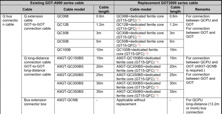
2.6.1 Q bus connection cable
(1) Utilization of cables in present use
The following shows the list for replacing the existing GOT-A900 series cables with the GOT2000 series
cables.
Table 2-8 Replacement cables of the GOT2000 series
Existing GOT-A900 series cable Replacement GOT2000 series cable Cable Cable model Cable
length Cable model
Cable
length Remarks
Q bus connectio n cable
Q extension cable GOT-to-GOT connection cable
QC06B 0.6m QC06B+dedicated ferrite core
(GT15-QFC) *1
0.6m For connection
between QCPU and GOT
For connection between GOT and GOT
QC12B 1.2m QC12B+dedicated ferrite core
(GT15-QFC) *1
1.2m
QC30B 3m QC30B+dedicated ferrite core
(GT15-QFC) *1
3m
QC50B 5m QC50B+dedicated ferrite core
(GT15-QFC) *1
5m
QC100B 10m QC100B+dedicated ferrite
core (GT15-QFC) *1
10m
Q long-distance connection cable GOT-to-GOT long-distance connection cable
A9GT-QC150BS 15m A9GT-QC150BS+dedicated ferrite core (GT15-QFC) *1
15m For connection
between QCPU and GOT (A9GT-QCNB is required.) For connection between GOT and GOT
A9GT-QC200BS 20m A9GT-QC200BS+dedicated ferrite core (GT15-QFC) *1
20m
A9GT-QC250BS 25m A9GT-QC250BS+dedicated ferrite core (GT15-QFC) *1
25m
A9GT-QC300BS 30m A9GT-QC300BS+dedicated ferrite core (GT15-QFC) *1
30m
A9GT-QC350BS 35m A9GT-QC350BS+dedicated ferrite core (GT15-QFC) *1
35m
Bus extension connector box
A9GT-QCNB - Applicable without
replacement
- For QCPU
long-distance (13.2m or more) bus connection *1 Purchase the ferrite cores from Mitsubishi Electric System & Service Co., Ltd. (The GT15-QFC or the GT15-AFC
includes two ferrite cores for a cable.)
(2) Replacing GOT when using multiple units of bus connection
When multiple GOT-A900 series are connected with the bus connection, one or more GOT-A900 series can be
replaced with the GOT2000 series by replacing all the bus connection cables with the GOT2000 series cables
or by attaching ferrite cores (listed in Section 2.6.1 (1)) to the GOT-A900 series cables. Therefore, the
GOT-A900 series and the GOT2000 series can exist in the same system.
GOT- A900 bus connection c able GOT- A900 bus connection c able
GOT-A900 series GOT-A900 series
GOT2000 bus co nnecti on cab le or
ferrite core a ttache d cabl e
GOT2000 series or GOT-A900 series
GOT2000 bus co nnection cab le or
ferrite core a ttached cabl e
[Issue No.]
GOT-A-0062-A
[Page]
22/63
[Title]
Precautions when Replacing GOT-A900 Series with GOT2000 Series
[Date of Issue]
January 2015
[Relevant Models]
GOT-A900 Series
→
GOT2000 Series (GT27 Models and GT25 Models)
TECHNICAL BULLETIN
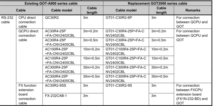
2.6.2 RS-232 cable
The following shows the list for replacing the existing GOT-A900 series cables with the GOT2000 series
cables.
Table 2-9 Replacement cables of the GOT2000 series
Existing GOT-A900 series cable Replacement GOT2000 series cable
Cable Cable model Cable
length Cable model
Cable
length Remarks
RS-232 cable
CPU direct connection cable
QC30R2 3m GT01-C30R2-6P 3m For connection
between QCPU and GOT QCPU direct connection cable AC30R4-25P +FA-CNV2402CBL 3m+0.2m GT01-C30R4-25P+FA-C NV2402CBL
3m+0.2m For connection
between QCPU and GOT AC30R4-25P +FA-CNV2405CBL 3m+0.5m GT01-C30R4-25P+FA-C NV2405CBL 3m+0.5m AC100R4-25P +FA-CNV2402CBL 10m+0.2m GT01-C100R4-25P+FA-C NV2402CBL 10m+0.2m AC100R4-25P +FA-CNV2405CBL 10m+0.5m GT01-C100R4-25P+FA-C NV2405CBL 10m+0.5m AC300R4-25P +FA-CNV2402CBL 30m+0.2m GT01-C300R4-25P+FA-C NV2402CBL 30m+0.2m AC300R4-25P +FA-CNV2405CBL 30m+0.5m GT01-C300R4-25P+FA-C NV2405CBL 30m+0.5m FX function extension board connection cable
AC30R2-9SS 3m GT01-C30R2-9S 3m For connection
between FXCPU extension board (FX1N-232-BD) and GOT
FX-232CAB-1 3m 3m
2.6.3 RS-422 cable
The following shows the list for replacing the existing GOT-A900 series cables with the GOT2000 series
cables.
Table 2-10 Replacement cables of the GOT2000 series
Existing GOT-A900 series cable Replacement GOT2000 series cable
Cable Cable model Cable
length Cable model
Cable
length Remarks
RS-422 cable QnA/A/FXC PU direct connection cable, Computer link cable, AJ65BT-G4 cable
AC30R4-25P 3m GT01-C30R4-25P 3m For connection between
QnA/A/FX(FX1, FX2, FX2c) CPU and GOT,
For connection between FA-CNV□CBL and GOT, For connection between FX-2PIF and GOT,
For connection between FX-422AW0 and GOT, For connection between serial communication module (AJ71QC24(N)-R4) and GOT, For connection between AJ65BT-G4-S3 and GOT
AC100R4-25P 10m GT01-C100R4-25
P
10m
AC300R4-25P 30m GT01-C300R4-25
P 30m RS-422 cable FXCPU direct connection cable FX function extension board connection cable
FX9GT-CAB0-150 1.5m GT01-C10R4-8P 1m For connection between FXCPU
(FX0, FX0S, FX0N, FX1S, FX1N, FX2N, FX2NC) and GOT For connection between FXCPU extension board (FX1N-422-BD, FX2N-422-BD) and GOT
FX9GT-CAB0 3m GT01-C30R4-8P 3m
FX9GT-CAB-10M 10m GT01-C100R4-8P 10m
AC30R4-25P +FX-422AW0
3m+1.5m GT01-C30R4-8P 3m
AC100R4-25P +FX-422AW0
10m+1.5m GT01-C100R4-8P 10m
AC300R4-25P +FX-422AW0
[Issue No.]
GOT-A-0062-A
[Page]
23/63
[Title]
Precautions when Replacing GOT-A900 Series with GOT2000 Series
[Date of Issue]
January 2015
[Relevant Models]
GOT-A900 Series
→
GOT2000 Series (GT27 Models and GT25 Models)
TECHNICAL BULLETIN
2.6.4 Network cable (Ethernet, MELSECNET/10, and CC-Link)
The GOT-A900 series network cables are applicable to the GOT2000 series.
2.6.5 Other cables
The following shows the list for replacing the existing GOT-A900 series cables with the GOT2000 series
cables.
Table 2-11 Treatment for other existing cables
Existing GOT-A900 series cable Replacement GOT2000 series cable
Cable Cable model Cable
length Cable model
Cable length
Printer cable CRT connection cable
AC30PIO-20P 3m For printer unit (GT15-PRN),
GT09-C30USB-5P
3m
For serial printer, cables prepared by user
Video image display coaxial cable AV50VG 5m Applicable without replacement
AV300VG 30m Applicable without replacement
Printer cable cables prepared by user Applicable without replacement
CRT connection cable cables prepared by user Applicable without replacement
◎: Available as-is ×: Not available
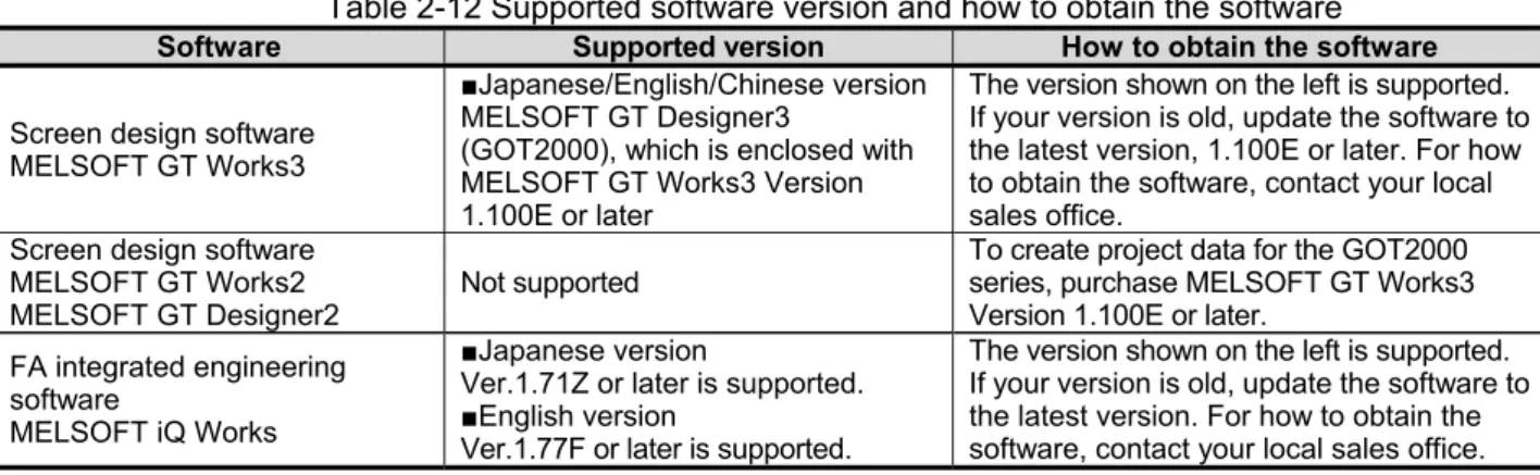
2.7 Software
To create project data for the GOT2000 series, MELSOFT GT Designer3 (GOT2000), which is included with
the screen design software MELSOFT GT Works3 (Version 1.100E or later), is needed.
For how to obtain the software in a specific version, refer to the following table.
Table 2-12 Supported software version and how to obtain the software
Software Supported version How to obtain the softwareScreen design software MELSOFT GT Works3
■Japanese/English/Chinese version
MELSOFT GT Designer3
(GOT2000), which is enclosed with MELSOFT GT Works3 Version 1.100E or later
The version shown on the left is supported. If your version is old, update the software to the latest version, 1.100E or later. For how to obtain the software, contact your local sales office.
Screen design software MELSOFT GT Works2 MELSOFT GT Designer2
Not supported
To create project data for the GOT2000 series, purchase MELSOFT GT Works3 Version 1.100E or later.
FA integrated engineering software
MELSOFT iQ Works
■Japanese version
Ver.1.71Z or later is supported.
■English version
Ver.1.77F or later is supported.
The version shown on the left is supported. If your version is old, update the software to the latest version. For how to obtain the software, contact your local sales office.
[Issue No.]
GOT-A-0062-A
[Page]
24/63
[Title]
Precautions when Replacing GOT-A900 Series with GOT2000 Series
[Date of Issue]
January 2015
[Relevant Models]
GOT-A900 Series
→
GOT2000 Series (GT27 Models and GT25 Models)
TECHNICAL BULLETIN
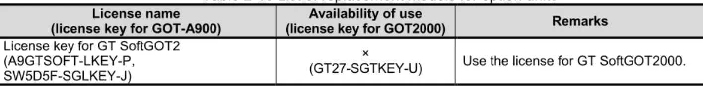
2.8 License
The GOT-A900 series licenses below cannot be used for the GOT2000 series. Please purchase the GOT2000
series licenses.
Table 2-13 List of replacement models for option units
License name(license key for GOT-A900)
Availability of use
(license key for GOT2000) Remarks
License key for GT SoftGOT2 (A9GTSOFT-LKEY-P SW5D5F-SGLKEY-J)
×
(GT27-SGTKEY-U) Use the license for GT SoftGOT2000.
×: Model change required
3. Comparison in specifications
The following describes the differences in the specifications between the GOT-A900 series and GOT2000
series. When considering a replacement of the GOT-A900 series with the GOT2000 series, check the
specifications of your current model and target model.
3.1 Hardware specifications
3.1.1 Comparison in hardware specifications
The following describes the comparison in the hardware specifications between the GOT-A900 series and
GOT2000 series.
(1) Lineup
Table 3-1 Lineup comparison
Item GOT-A900
GOT2000 GT27
standard
GT27 white
GT25 standard
GT25 white
Front face color Black Black White Black White
LCD size
15" XGA - ◎ - - -
12.1" SVGA
(12” SVGA) ◎ ◎ ◎ ◎ -
10.4" SVGA - ◎ - - -
10.4" VGA
(10” VGA) ◎ ◎ ◎ ◎ ◎
8.4" SVGA - ◎ - ◎ ◎
8.4" VGA ◎ ◎ - - -
9” 640 × 400 dots ◎ - - - -
7” 480 × 234 dots ◎ - - - -
6" QVGA ◎ - - - -
Number of display colors
65536 colors - ◎ ◎ ◎ ◎
256 colors ◎ - - - -
16 colors ◎ - - - -
8 colors ◎ - - - -
2 color
(yellow orange, black)
◎ - - - -
2 color
(monochrome) ◎ - - - -
[Issue No.]
GOT-A-0062-A
[Page]
25/63
[Title]
Precautions when Replacing GOT-A900 Series with GOT2000 Series
[Date of Issue]
January 2015
[Relevant Models]
GOT-A900 Series
→
GOT2000 Series (GT27 Models and GT25 Models)
TECHNICAL BULLETIN
(2) External dimensions
For the panel cutting dimensions and mounting intervals, refer to Section 3.1.2.
■
12” (GOT-A900 series)
■
12.1” (GOT2000 series)
238
22
7
10
10 33.5 245
312 15.4
43
49
301
6
245 33.5
A985GOT(-V)
GT2712
GT2512
31624
6
22
7
10
10
52
6
241
241
301
■
10” (GOT-A900 series)
■
10.4” (GOT2000 series)
288 235
208
40
46
6
199
10
1
0
297 229 15.4 31
34 A975GOT
A970GOT GT2710GT2510
303 208
228
288
218
19
9
10
10
52
[Issue No.]
GOT-A-0062-A
[Page]
26/63
[Title]
Precautions when Replacing GOT-A900 Series with GOT2000 Series
[Date of Issue]
January 2015
[Relevant Models]
GOT-A900 Series
→
GOT2000 Series (GT27 Models and GT25 Models)
TECHNICAL BULLETIN
■
9” (GOT-A900 series)
■
8.4” (GOT2000series)
257
43
49
6
192
18
2
10
10
204
268 198 15.4 32
35
A960GOT
GT2708GT2508
241
166 37.5
37.5
226 171.6 175 19
4
10
10
52
[Issue No.]
GOT-A-0062-A
[Page]
27/63
[Title]
Precautions when Replacing GOT-A900 Series with GOT2000 Series
[Date of Issue]
January 2015
[Relevant Models]
GOT-A900 Series
→
GOT2000 Series (GT27 Models and GT25 Models)
TECHNICAL BULLETIN
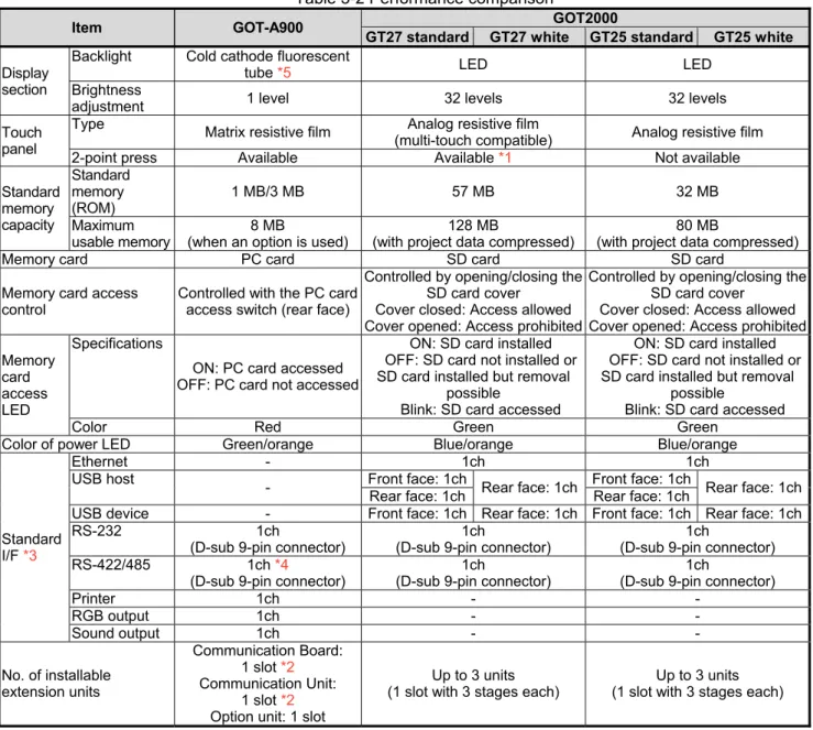
(3) Performance specifications
The following describes the comparison in the performance specifications between the GOT-A900 series and
GOT2000 series.
Table 3-2 Performance comparison
Item GOT-A900 GOT2000
GT27 standard GT27 white GT25 standard GT25 white
Display section
Backlight Cold cathode fluorescent
tube *5 LED LED
Brightness
adjustment 1 level 32 levels 32 levels
Touch panel
Type Matrix resistive film Analog resistive film
(multi-touch compatible) Analog resistive film
2-point press Available Available *1 Not available
Standard memory capacity Standard memory (ROM)
1 MB/3 MB 57 MB 32 MB
Maximum usable memory
8 MB
(when an option is used)
128 MB
(with project data compressed)
80 MB
(with project data compressed)
Memory card PC card SD card SD card
Memory card access control
Controlled with the PC card access switch (rear face)
Controlled by opening/closing the SD card cover
Cover closed: Access allowed Cover opened: Access prohibited
Controlled by opening/closing the SD card cover
Cover closed: Access allowed Cover opened: Access prohibited
Memory card access LED
Specifications
ON: PC card accessed OFF: PC card not accessed
ON: SD card installed OFF: SD card not installed or SD card installed but removal
possible
Blink: SD card accessed
ON: SD card installed OFF: SD card not installed or SD card installed but removal
possible
Blink: SD card accessed
Color Red Green Green
Color of power LED Green/orange Blue/orange Blue/orange
Standard I/F *3
Ethernet - 1ch 1ch
USB host
- Front face: 1ch Rear face: 1ch Front face: 1ch Rear face: 1ch
Rear face: 1ch Rear face: 1ch
USB device - Front face: 1ch Rear face: 1ch Front face: 1ch Rear face: 1ch
RS-232 1ch
(D-sub 9-pin connector)
1ch
(D-sub 9-pin connector)
1ch
(D-sub 9-pin connector)
RS-422/485 1ch *4
(D-sub 9-pin connector)
1ch
(D-sub 9-pin connector)
1ch
(D-sub 9-pin connector)
Printer 1ch - -
RGB output 1ch - -
Sound output 1ch - -
No. of installable extension units
Communication Board: 1 slot *2
Communication Unit: 1 slot *2
Option unit: 1 slot
Up to 3 units (1 slot with 3 stages each)
Up to 3 units (1 slot with 3 stages each)
*1 Note the there are precautions on the arrangement of 2-point press switches. For the details, refer to Section 3.1.6. *2 The communication board and communication unit cannot be used together.
*3 The equipped I/F differs depending on the model of the GOT-A900 series. *4 The GOT-A900 series support RS-422 only.