A Unified Test and Fault-Tolerant Multicast Solution
for Network-on-Chip Designs*
Dong Xiang School of Software Tsinghua University Beijing 100084, China
Krishnendu Chakrabarty EE Dept.
Duke University Durham, NC 27708, USA
Hideo Fujiwara Faculty of Informatics Osaka Gakuin University
Osaka 564-8511, Japan
Abstract—We present a unified test technique that targets all the components of a network-on-chip design. The proposed technique targets faults in links, routers, and cores. Link faults are first located using built-in self-test hardware inserted in the routers. Test packets for routers are delivered to the routers via the fault-free links and routers identified in the previous steps. A test packet can be corrupted by faulty links or routers, therefore, it is delivered across only previously identified fault-free routers/links. Test packet delivery for routers is implemented as a fault-tolerant unicast-based multicast scheme within the tested part of the network-on-chip. After all faulty routers are identified, a new fault-tolerant unicast-based multicast routing technique is proposed to deliver test packets for the cores. Identical cores share the same test set, and they are tested within the same test session. Simulation results highlight the effectiveness of the proposed method in reducing test time.
Index Terms—Core testing, fault-tolerant unicast-based multicast, NOC testing, on-chip networks, router testing.
I. INTRODUCTION
A network-on-chip (NOC) has emerged as a promising communication paradigm for core-based system chips [3], [10]. Testing complex and embedded NOCs however remains a challenging problem. To reduce test cost, reuse of the network for NOC test delivery is an attractive solution [1], [7]–[9], [14], [15], [19], [27]–[32].
Most previous test methods [1], [7]–[9], [14], [19], [28]–[32] disregarded network failures when delivering test packets. Our method targets test delivery for NOC testing in a NOC with multiple link/router failures. With this objective, we present a new fault-tolerant unicast-based multicast algorithm for test-packet delivery.
We present a unified methodology to test links, routers and cores. Interconnects are tested by built-in self-test (BIST) and BIST logic is inserted within each router. However, BIST alone is not sufficient to achieve high fault coverage for routers and complex cores. Therefore, routers and cores are tested using deterministic test data in order to obtain complete fault coverage. As in [32], we assume that routers with the same number of terminals are identical; therefore, they share the same test set. A new fault-tolerant unicast-based multicast procedure is proposed to deliver test packets for routers. After the status of all routers
*This work is supported in part by the National Science Foundation of China under grants 61170063 and 61373021, and the research foundation from the Ministry of Science and Technology under grant 2016YFB1000200.
have been identified, our method delivers test packets for the cores based on a different fault-tolerant multicast method. We explain the difference between these two multicast algorithms, used for router testing and core testing, respectively, later in this section.
A test set is generated for different classes of cores/routers separately. Each test packet for cores is delivered to all cores in the corresponding class by using the proposed fault-tolerant unicast-based multicast algorithm. Many cores differ only slightly in terms of the logic implementation; we refer to these as similar cores; these cores can still share most test packets. Two similar cores can be merged into the same circuit for test generation purpose as in [29]. Tests for two cores can be generated on the merged circuit as in the method presented in [29]. The new method can also be utilized when the NOC contains completely different cores. In this case, the unicast-based multicast procedure for core testing degrades to a unicast scheme.
We do not present a new low-power testing scheme in this paper. The low-power test application scheme from [29], [31] utilized here, and it is combined with the power-aware test scheduling from [29]. The test responses are compacted by an on-chip X-tolerant multiple-input signature-register (MISR) as in [31]. The compacted test responses in the MISR are delivered back to the ATE after all test vectors have been applied. This can also reduce test power consumption during NOC testing.
Some related concepts are introduced first. A unicast delivers a packet from a single core, called the source, to a single destination. A multicast delivers a packet from a single core called the source to multiple cores in the NOC [20]. A unicast-based multicast scheme completes multicast by using multiple unicast steps, therefore, it is not necessary to modify the unicast router architecture [20]. The new method is also applicable when the NOC contains completely different cores. In this case, the unicast-based multicast degrades to a unicast.
Let the address of a node x be represented by (σ1(x), σ2(x), . . ., σn(x)). The binary relation dimension-order, denoted <d, is defined between two nodes x and y as follows: x <d y if and only if either x= y or there exists an integer j such that σj(x) < σj(y) and σi(x) = σi(y) for all i, 0 ≤ i ≤ j − 1. For any set of node addresses, they can be arranged in a unique sequence according to the <d relation. A sequence of nodes x1, x2, . . . , xmis a dimension-ordered chain if and only if, (1)
IEEE International Test Conference 2016 (ITC'16), Nov. 15-17, 2016
ATE
(0,7) (7,7)
v1 v2
v3 v4
v5
v
v v
6
7 8
(0,0) (7,0)
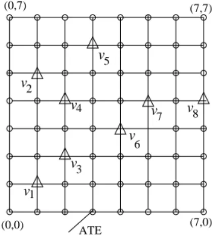
Fig. 1. An illustration of a dimension-ordered chain.
xi<dxi+1 for 1 ≤ i < m, or (2) xi<dxi−1for 1 < i ≤ m. Let u <dv <dw <dz. Two unicast packets can be delivered from u to v, and from w to z concurrently without any common link [20]. Two unicast packets can also be delivered from v to u, and z to w with disjoints link by using X-Y routing in a 2D mesh/torus. The X-Y routing in a 2D torus requires two virtual channels unlike deterministic routing in a 2D mesh, which uses just a single virtual channel. Fig. 1 presents an example dimension-ordered chain (1,1) (v1), (1,5)(v2), (2,2)(v3), (2,4) (v4), (3,6) (v5), (4,3) (v6), (5,4) (v7), and (7,4) (v8) with eight nodes.
The new method handles the testing of links, routers and cores in a single flow. A test packet is delivered using pre-determined fault-free routers/links (IFFRs/IFFLs) in order to ensure that faulty routers/links do not corrupt the test packet. The routing scheme for test delivery conforms to the baseline routing scheme of the NOC. We assume that the NOC is designed by the baseline fault-tolerant routing scheme, which utilizes virtual networks to avoid deadlocks. Any other fault-tolerant routing algorithm can also be used as the baseline routing scheme.
The main contributions of the proposed method include: (1) A new test delivery scheme for router testing is presented by forwarding a test packet to a number of identified fault-free routers (IFFRs) first. Test delivery for routers is is presented. This method first forwards a test packet to a number of identified fault-free routers (IFFRs). Test delivery for routers is formulated as a fault-tolerant multicast problem within the IFFRs/IFFLs. (2) Test delivery and scan testing for routers can proceed concurrently because the proposed router testing scheme does not deliver test packets for routers using a potentially faulty router/link or a router under test. This important feature, not provided by prior methods in [15], [31], can significantly reduce test cost. (3) A new fault-tolerant unicast-based multicast algorithm is proposed for core testing in a NOC that may contain both link and router failures.
In the rest of this paper, we first present related previous work in Section 2. Router testing is partitioned into multiple test sessions in Section 3. Identical routers, which can be accessed from the ATE via the IFFRs concurrently, are tested in the same test session. Router testing is addressed using a fault-tolerant unicast-based multicast algorithm. Test packets are delivered to the selected IFFRs first, and they are then forwarded to the
routers under test in the last unicast step. The new fault-tolerant unicast-based multicast algorithm for core testing is described in Section 4. Experimental results are presented in Section 5. The paper is concluded in Section 6.
II. RELATEDPREVIOUSWORK
Reuse of the communication platform [7]–[9], [11] is a cost-effective test technique for cores in a NOC-based multicore chip. An inefficient solution to the NOC testing problem does not use the full NOC bandwidth for testing and instead delivers tests to cores by one-to-one unicast operations sequentially. An algorithm based on the list-scheduling technique was proposed to minimize the test cost. Cota and Liu [9] proposed a new test scheduling scheme for NOC testing with multiple-port automatic test equipment (ATE). The way to deliver test packets by unicast is likely to increase test time considerably and thereby leads to higher test cost [7]–[9].
The method in [15] exploits the inherent parallelism of the data transport mechanism to reduce test cost for interconnect testing as well as the test application time. Test scheduling algorithms were developed based on a unicast scheme and a multicast presented for sequential and concurrent test data transport. Techniques have also been proposed to improve interconnect reuse for NOC testing [9], [11], [27]. A number of design for testability techniques have been proposed for NOC testing [2], [11], [22], [27].
The article in [23] reviewed the failure mechanisms, fault models, diagnosis techniques, and fault-tolerance methods in on-chip networks, and surveyed and summarized the research in the past years. Kohler and Radetzski in [17] presented a fault-adaptive deflection routing mechanism that takes the detailed fault status of NoC crossbar connections into account. The fault status is obtained through distributed online diagnosis that distinguishes between permanent and transient faults.
Consider an example NOC with 100 cores. There may exist a very small number of different classes of cores in the NOC [25]. Xiang et al. in [29] proposed a unicast-based multicast algorithm for test delivery to logic cores using the NOC as the interconnect fabric. All identical cores share the same test packets. A test packet can be multicast to the identical cores using a unicast-based multicast algorithm [29], [31]. Test responses are collected along the reverse paths of the multicast tree in [29]. Test responses with unknown signals are compacted on-chip using an unknown-tolerant MISR-based response compactor in [31]. A new unicast-based multicast approach was proposed to deliver test packets for router testing in [32]. This method could duplicate a test packet to intermediate nodes in the path of the baseline routing scheme. Therefore, the switch achitecture and the mechanism to avoid consumption channel deadlocks, are quite different.
Forese et al. [14] proposed a new test compression scheme for core testing, where only the seeds are delivered to the cores. A test-delivery optimization algorithm was proposed by Agrawal et al. in [1] for NOC-based SOCs with hundreds of cores by using a new dynamic programming model. Ramdas and Sinanoglu in [24] proposed a comparison-based test access mechanism (TAM) that is capable of handling spare identical
(7,7)
1
2 2
3
3 3
3 4
4
4 4 4
5 4 5
5 5
5
5
6 6
6
6
7 7 6 7
7
8 8 8
8 9
9
10 10 10 10 10
10 10 10 10 10 10 10 10 10 10 10 10 10
10
10 10
10
10
11 11
11
(0,0) ATE
11 (7,0) (0,7)
6 7
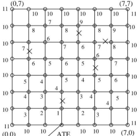
Fig. 2. The 8 × 8 on-chip network with five link failures.
cores. A comprehensive end-to-end solution was proposed for error correction, data collection, and defect diagnosis and replacement for on-chip networks in Shamshiri and Cheng [26]. Previous methods such as [7]–[9], [11], [14], [19], [29], [31], [32], which reuses the interconnects to deliver test data, did not consider the impact of faulty components on test-data transfer. Delivering a test packet across a faulty router/link can corrupt the test data, and this problem cannot be disregarded. The unicast test delivery techniques in [7], [9], [11], [14], [19] can incur high test cost. This is key motivation for proposed work on a fault-tolerant multicast solution for NOC core and router testing.
III. ROUTERTESTING WITHMULTIPLETESTSESSIONS
The physical links are tested by using a built-in self-test (BIST) scheme as in [8], [32]. Assume that the8×8 mesh-based NOC as shown in Fig. 2 contains five link failures, which have been identified by the BIST scheme for physical interconnects. Our fault-tolerant unicast-based multicast algorithm for router testing partitions the set of routers into multiple subsets, where each subset of routers can be accessed by the ATE via IFFRs or IFFLs in a single test session. We call this entire procedure, which delivers test packets to the subset of routers, a test session. Our method selects the same number of IFFRs in this paper, which can be smaller. Any test packet is delivered to all selected IFFRs first. The selected IFFRs deliver the received test packet to all routers under test separately in a single unicast step if the number of the selected IFFRs is equal to the number of routers under test in this test session.
The test packets are delivered from the ATE step by step to all routers in a single test session. Routers of the same degree fall into the same class [32], which share the same test set. All routers in the same class, that are accessible from the IFFRs and IFFLs directly, can be tested concurrently in the same test session. It is necessary for the paths in the last unicast step, from all IFFRs to the routers under test, to have no conjoint physical link. This can avoid resource contention. As shown in Fig. 2, the numbers attached to the routers indicate the test sessions. It is shown that the proposed test scheme for routers partitions router testing into eleven test sessions. All test packets for the routers tested in the same test session are delivered to them in tandem.
A test packet is first sent to all selected IFFRs vi′ (1 ≤ i ≤ k), where all IFFRs and the source (s) connected to the ATE are arranged as a dimension-ordered chain, k routers v1-vk are tested in a single test session. Fig. 2 shows that the ATE is in the middle of the bottom row in the mesh. It can be at any location of the NOC.
The proposed method completes a multicast with multiple unicast steps, which is different from [20]. The ATE only involves in the first unicast step like the methods presented in [29], [31]. The most important difference between the proposed method and the methods in [29], [31] is the baseline routing scheme, which avoids link failures, and routers/links that have not been identified as fault-free. Therefore, the fault-tolerant routing scheme is also quite different from any previous ones. As shown in Figs. 3, 5, and 6, any test packet is not delivered across any components connected by dashed lines. The proposed fault-tolerant unicast-based multicast algorithm for router testing is quite different from the ones in [21], [32] that allows test data duplication at the intermediate routers in each unicast step, therefore, the crossbar switch architecture, and the consumption channel design are more complicated.
The multicast tree is kept in the header flits at the ATE as the unicast-based multicast algorithm like the method in [20], which is implemented by just forwarding the dimension-ordered chain to the root of the multicast tree first. Each router, that receives the test packet in the previous unicast step, determines its successors. A subset of destinations ordered into a dimension-ordered chain is forwarded to the corresponding successors. The process continues until all destinations have received the test packet.
Our method does not use any of the routers under test as an intermediate node in order to avoid corrupting the test packet. This makes test delivery more complex because a fault-tolerant unicast-based multicast algorithm must be used. However, this requirement makes test delivery and test application for router testing concurrent, which is a very attractive feature. This feature can reduce test cost significantly compared to the method in [32]. The method in [32] handles test application inside a router and test delivery in the network sequentially. Test packets are applied to the router under test when its consumption channel has been filled. Test delivery is started again until all tests have been delivered to the router and applied.
The test packet is delivered to all selected IFFRs, which are ordered into a dimension-ordered chain. After the test packet has been delivered to all selected IFFRs, they are delivered to all routers under test concurrently in a single unicast step. Assume that N identical routers are tested concurrently in the test session, the proposed method requires log2N+ 2 unicast steps to complete the multicast operation for each test packet.
Link contention is also no longer an issue because of the virtual channel router design and the MISR-based test response collection scheme. The reason why we arrange the destinations of the multicast operation into a dimension-order chain is that we still need to reduce the amount of link contention in order to reduce test delivery time.
An MISR is inserted into each router. Synchronization for
(a) (b) v
v
v v
v v
2
3 4
5
v’ v’
v’
v’ v’
v’
v’
v’ v’ v’
v’ v’
2 3
4
3 5
(c) v
v
v v
v
2
v’ v’
v’ v’
v’ v’
2
v’ v v’
v v’
v v’ v
v v’ v’ v4 1
4
5
5 5 v
v v v
v v
1
2 3
4
5 6 1
2 3
4
5
6
(7,0)
(0,7) (7,7) (0,7) (7,7)
(7,0)
(0,7) (7,7)
(7,0)
(0,7) (7,7)
1
1
v 4
5
5 4
1 1 1
2
2
5 5
6
6 3
3
6
6
3
3 4
4
6
6
1 2
3
4
4 5
(0,0) (0,0) (d)
(0,0)
(0,0) (7,0)
ATE
ATE ATE
ATE
Fig. 3. The fault-tolerant unicast-based multicast algorithm to deliver test data for routers in a faulty 8x8 mesh with link failures: (a) the first and second unicast steps, (b) the third unicast step, (c) the 4th unicast step, and (d) 5th unicast step.
v
v’1 v1 v’25 2 ATE v’3 v3 v’4 v4 v’5 v5 v’6 v6
3 4
5 4 5
4 3
5 4
1 2
Fig. 4. The multicast tree to deliver test data for routers tested in the 5th test session.
each unicast step is necessary because our method only delivers the final compacted responses back to the ATE. The test response in the MISR-based response compactor is delivered back to the ATE separately after all test packets have been delivered to the routers under test. Therefore, we assume that router failures for the routers under test can be identified after a test session has been completed.
Selection of IFFRs for each test session is also important. First, the routers tested in the previous test session can be very good candidates. Other IFFRs can be selected, which access the remaining routers along disjoint paths when the IFFRs tested by the previous test session are not sufficient for this purpose.
We assume that the router connected to the ATE is fault-free. The ATE delivers tests for the 4-degree router at node (3,1) in the first test session, which is identified fault-free. Two 4-degree routers at node (2,1) and (4,1) are tested in the second test session. There is only a single IFFR (3,1) as shown in Fig. 2 in the second test session. Our method sends a test packet to the router (3,1) in the first unicast step, which is delivered to the router (2,1) in the second unicast step from the router (3,1).
The test packet is delivered to the router (4,1) from the router (3,1) in the third unicast step.
Fig. 3 presents the five unicast steps in order to test all six 4-degree routers at nodes (1,3) (v1), (2,4) (v2), (3,3) (v3), (4,5) (v4), (5,3) (v5), and (6,2) (v6). Six IFFRs at nodes (1,2) (v′1), (2,3) (v2′), (3,2) (v′3), (4,4) (v′4), (5,2) (v5′), and (6,1) (v6′) are selected to deliver test packets. The selected six IFFRs are tested in the previous test session as shown in Fig. 2.
The twelve routers are ordered into a dimension-ordered chain: v′1, v1, v′2, v2, ATE, v′3, v3, v4′, v4, v5′, v5, v6′, v6. Fig. 4 presents the multicast tree for the six 4-degree routers tested in the 5th test session. The test packet is delivered to v4′ from the ATE in the first unicast step. The router v′4 forwards the packet to v3′ in the second unicast step. In the third unicast step, the packets at v3′ and v′4 are delivered to v′2 and v′5, respectively. More details on the unicast-based multicast algorithm are presented in Figs. 4 and 3.
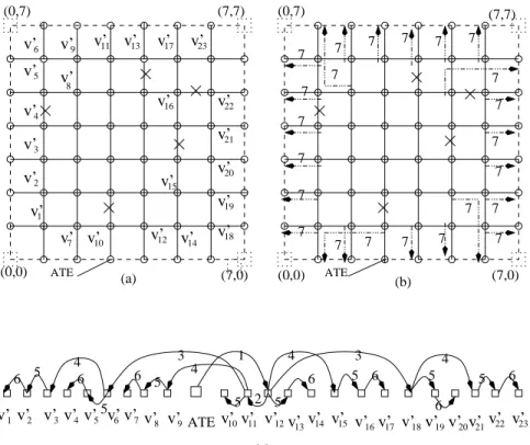
Fig. 5 presents the 11th test session. All 3-degree routers are tested concurrently in the same test session. Totally, 23 3-degree routers v1-v23 are tested in the test session. Our method selects twenty-three IFFRs v′1-v′23to deliver test packets for the routers under test in this test session as shown in Fig. 5(a). Fig. 5(b) shows that all the selected IFFRs deliver the test packets to separate 3-degree routers under test in the last unicast step. Fig. 5(c) presents the multicast tree along which a test packet is
v’ v’ v’ v’
v’ v’ v’ v’ v’
v’
v’ v’
v’
(c) 7 7 7 7 7 7
7
7 7 7 7 7
7 7 7
7 7
7 (7,0)
(0,7) (7,7)
(0,0) (7,0)
(0,7) (7,7)
7 7 7 7
7
v’ v’ v’
v’7 8
v’10
v’ v’
v’15 v’ v’
v’ v’ v’ v’ v’6v’ v’ v’ v’ v’ v’ v’ v’v’ v’ v’ 17
v’ v’14 v’ v’ v’11 v’10
13 15
12 16 18 19 20 21 22 23
5 8 9
1 2 3 4 7
2 3 4 5
6 9 11 13 17 23
ATE
1 4 3 4
2 3
4 5
5 6
4
5 5 6
6
5
6 5 6 5 5 6
6
ATE ATE
(a) (b) (0,0)
16
12 14
22
21
20
19
18
v’1
Fig. 5. The unicast-based multicast algorithm in the 11th test session: (a) the selected identified fault-free routers, (b) the last unicast step, (c) the unicast-based multicast tree.
v
v
1
v2 3
v’
v’ v’
v’
2 3
2
v4
ATE 4
(0,0) 1
(0,7) 3 (7,7)
4 4
4 4
1
3
(7,0)
Fig. 6. Illustration of the unicast-based multicast algorithm to deliver test data in the 12th test session.
delivered from the ATE to all the selected IFFRs in six unicast steps.
Fig. 6 presents test delivery for the four 2-degree routers. Four IFFRs (1,0), (1,7), (6,0) and (6,7) are selected. A test packet at the ATE is delivered to v′1in the first unicast step, and forwarded to v′2 in the second unicast step as shown in Fig. 6. The test packets at v1′ and v2′ are forwarded to v′4 and v3′ in the third unicast step, respectively, as shown in Fig. 6. The test packets at v1′-v4′ are delivered to nodes v1-v4, respectively in the 4th unicast step. The number of unicast steps for a test session does not affect the test cost because the ATE can deliver a test packet in each unicast step.
route computation arbitration unit
x+
x−
y+ y− x−
x+
y+
y−
switch
MISR
MUX DMUX
DMUX
DMUX
DMUX
scan chains
combinational outputs
from the processor for operational packets MUXto scanchains
to the injection port from the injection
port of the IFFR
Fig. 7. The DFT architecture to implement test delivery and test application for router testing.
Fig. 7 presents the design for testability (DFT) architecture for router testing. Four separate demultiplexers (DMUX) are inserted into four different input ports. One of the two outputs of a DMUX is connected to the input port. The other output of the DMUX is connected to the multiplexer (MUX), whose output is connected to scan chains. The output of the MUX can be up to the width (d) of the physical channels, which drives up to d scan chains. The scan-out signals are connected to the MISR for test response compaction. The outputs from other combinational logic are also connected to the MISR. The output of the MISR is connected to another MUX, whose output is the injection port. Another input of the MUX is the channel from the local processor for operational packet injection.
IV. CORETESTINGBASED ON AFAULT-TOLERANT
UNICAST-BASEDMULTICASTSCHEME
All identical cores share the same test set as in the router-testing method presented in Section III. The core testing
core-testing() {
1) Partition all cores into classes C = {C1, C2, . . . , Ck}, where cores in the same class are identical.
2) while (C6= ∅), do
a) Select a core class Ci ∈ C, C ← C − Ci; sort the cores detected by v in the NOC into a dimension-ordered chain D.
b) while (TCi 6= ∅), do i) TCi ← TCi− {v};
ii) Call deliver(c′, D) to deliver the test packet from the router connected to the ATE to all cores in the dimension-ordered chain D.
3) Deliver back all test responses compacted at the cores to the ATE.
}
Fig. 8. Pseudocode for test delivery for core testing.
problem is described as a fault-tolerant unicast-based multicast problem when some routers and links have been identified faulty. The main difference between the new mathod and the one proposed in [29] is the baseline routing scheme. The method in [29] used a dimension-order routing scheme, which did not consider impact of faulty components. The faulty routers/links can corrupt the test data when delivering a packet across the faulty components. A new fault-tolerant routing algorithm is provided with a new virtual network partitioning. More details on the fault-tolerant routing algorithm are not presented for simplicity. Others fault-tolerant routing algorithms can also be used as the baseline routing scheme.
We propose a new fault-tolerant unicast-based multicast algorithm to deliver test packets to all identical cores in a single test session. The new fault-tolerant multicast algorithm is different from the one for router testing in Section III. The new fault-tolerant multicast algorithm does not select IFFRs for test delivery unlike the fault-tolerant multicast algorithm in Section III, which also does not constrain test delivery inside the sub-network with tested components. The new fault-tolerant unicast-based multicast algorithm uses all available routers/links in the network to deliver test packets.
Test delivery in the faulty network and test application inside cores under test can be proceeded concurrently unlike the router testing method in [32]. The way to handle test responses is similar to [31], an unknown-tolerant MISR is used to compact test responses. The final compacted test response is delivered packet to the ATE by a single packet after all tests have been applied. Unlike to method in Section III as presented in Fig. 7, test packets are delivered to the consumption channel as shown in Fig. 11.
Consider a multicast operation in a 2D mesh. All identical cores are ordered in a dimension-ordered chain c1, c2, . . . , cl. A recursive fault-tolerant multicast procedure in Fig. 8 is proposed for test delivery. All test packets for the same class of cores are delivered sequentially in a single test session.
As shown in Fig. 8, all cores fall into a couple of classes C1, C2, . . . , Ck. Our method tests cores class by class until all cores
deliver(c′,D) {
1) If (|D| = 2), deliver the packet to the remaining node d by calling fault-tolerant-route(c′, d);
2) Else, divide D into two equal subsets D1 and D2. 3) If (c′ is in the lower half D1),
a) deliver the test packet from c′ to the first node c2 in the upper half D2 with fault-tolerant-route(c′, c2);
b) call deliver(c2, D2) at c2, call deliver(c′, D1) at c′. 4) If(c′ is in the upper half D2),
a) deliver the packet from c′to the last node c1in the lower half D1 with fault-tolerant-route(c′, c1);
b) call deliver(c1, D1) at c1, call deliver(c′, D2) at c′. }
Fig. 9. The recursive procedure to multicast a test packet.
2 3
4
5
8
(0,0) (0,7)
6
7
v v
v
v v
v v
(7,0) (7,7)
v1
ATE(a)
v2 v1
1 2
4 3 4 4 3 4
v3 ATE v4 v5 v6 v7 v8 (b)
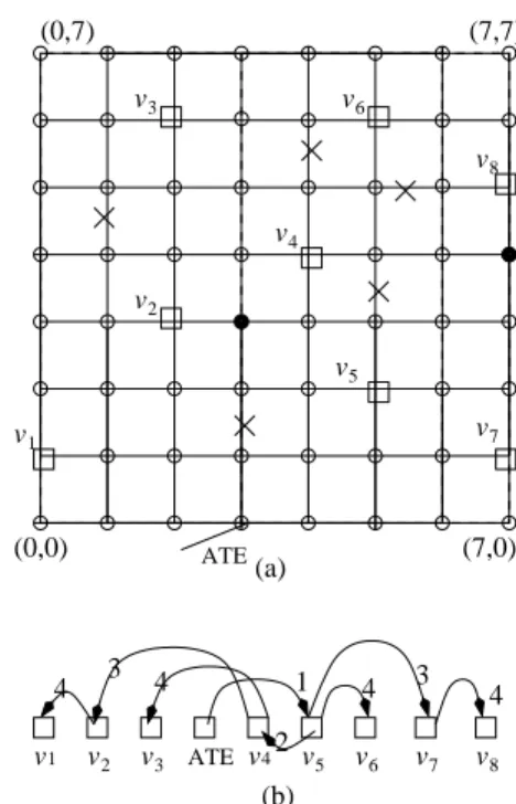
Fig. 10. Fault-tolerant unicast-based multicast to deliver test data for cores: (a) cores under test, (b) the multicast tree.
have been handled. Cores in the same class are ordered into a dimension-ordered chain. A recursive algorithm is proposed to deliver a test packet to all cores using the proposed fault-tolerant unicast-based multicast algorithm.
The pseudo-code of the fault-tolerant unicast-based multicast algorithm is presented in Figs. 8- 9. The test packet is delivered to a node c′from the node connected to the ATE. The cores that have at least one fault covered by the test vector are arranged into a dimension-ordered chain D. The core sequence is divided into two equal parts D1and D2. Let c′be in the lower part D1; it delivers the test packet to the first node c2 in the upper half D2, where c2 will be responsible for the test packet delivery to all other cores in the D2using the same procedure recursively, and c′ manages test packet delivery of the first part. If the core c′ is in the upper part D2, then it sends the packet to the last node c1 in the first part D1. The core c1 manages test packet delivery for D1, and the core c′ handles test packet delivery
of the second part recursively. Our method needs log2N + 1 unicast steps to deliver a test packet to all destinations, where N is the number of destinations related to the multicast operation. In contrast to [20], the fault-tolerant unicast-based multicast can be completed with multiple unicast steps. Therefore, the ATE can deliver the second test packet in the second unicast step. The procedure fault-tolerant-route(c′,d) delivers a packet from c′ to d using the baseline fault-tolerant routing algorithm. The multicast tree is kept in the header flits, and it is implemented by simply forwarding the dimension-ordered chain to the root of the multicast tree. Each core, which receives the test packet in the previous unicast step, determines its successors by running the procedure presented in Figs. 8- 9. A subset of destinations ordered into a dimension-ordered chain is forwarded to the corresponding successors. The process continues until all destinations have received the test packet.
Let us consider the 8 × 8 mesh shown in Fig. 10(a). The address sequence (0,1) (v1), (2,3) (v2), (2,6) (v3), (4,4) (v4), (5,2) (v5), (5,6) (v7), (7,1) (v6), and (7,5) (v8) is a dimension-ordered chain. Fig. 10(b) presents the multicast tree used to deliver a test packet from the router connected to the ATE to all destinations in four unicast steps. The numbers at the arrowed lines present the unicast steps. Unlike the method in [29], we assume that the NOC is designed based on the baseline fault-tolerant routing algorithm. Therefore, a test packet is delivered to the destinations based on the new fault-tolerant routing scheme instead of dimension-order routing. The baseline fault-tolerant routing algorithm can be replaced by any other fault-tolerant routing algorithms.
The node that receives the test packet from the ATE must forward the test packet to multiple nodes in the following consecutive unicast steps. That node must keep the test packet in the consumption buffer in all the unicast steps. As shown in Fig. 10(b), a bottleneck can occur at node v1 because the node v1 as shown in Fig. 10(b) must forward the test packet to other destinations. The later packets may have to wait until the consumption buffer at v1, and test packet delivery is delayed.
The number of extra pins must be kept small. Each core requires a number of scan-in and scan-out pins, which can make the total number of extra pins large when the number of cores in the NOC is large. The number of test selection pins of the scan flip-flops for all cores can also be high if each core uses a separate test selection pin. Note that only cores of the same class can be tested concurrently. Nevertheless, we explain below why the proposed method is very efficient in terms of I/O pin overhead.
All scan-in pins in a core are driven by the consumption buffer, therefore, no extra scan-in pins are necessary. All scan-out pins are connected to the MISR, where the output of the MISR is connected to the injection buffer. The injection buffer is the interface between the local router and the network, which injects packets to the network for the next unicast step or delivers the final response packet to the ATE. In our method, all cores share the same test selection pin as shown in Fig. 11. Therefore, the number of extra pins to control scan testing in a NOC is just one.
e MUX from the processor operating packets MISR
the injection buffer to the network global extra pin
M test
R’1 clk c
M R’k test clk1
clk1 x
x c clk
R k Rk−1 R1
1 0 0
hold
x1 cx
: scan chain : scan flip−flop
SI 1 SI2 SIn−1 SIn
hold
gating logic
to the scan trees
test packets operating packets to the processor c DMUX
x from the consumption buffer
Fig. 11. The DFT architecture for core testing.
Our method needs a total of k extra pin as shown in Fig. 11, where each extra pin drives a class of cores and k is the number of different classes of cores (k is set to to be no more than 4 in this paper). If control signal c= 1, the corresponding class of cores is under test. The number of extra pins can be further reduced by using an extra register.
V. EXPERIMENTALRESULTS
We have implemented the proposed method, and the methods in [29] and [15]. Single stuck-at faults are considered in routers and cores in this paper. The testing of NOC for transition faults can be carried out in a similar manner. We assume that test application is started immediately after a test packet has been received at each core. As in previous work, at most three packets can be kept at the injection buffer and the consumption buffer at each router [13]. The consumption buffer is the interface from the network to the processor, and the injection buffer is the interface from the processor to the network.
Assume that each physical channel has two virtual channels in the NOC. The start-up and receipt latency are are set to 10 clock cycles in all simulation results [13]. The consumption buffer for each core can keep up to three test packets, while the injection buffer provides sufficient capacity to keep three packets. Two adjacent routers transfer a single flit data for each clock cycle, where a flit contains 32 bit data.
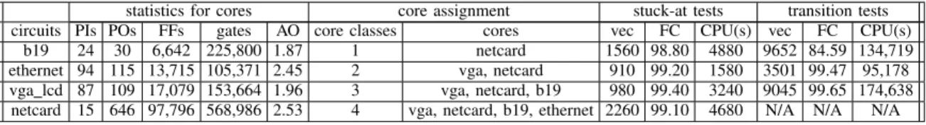
The proposed method has been evaluated using the two largest IWLS2005 circuits ethernet and vga lcd. An even larger benchmark circuit netcard and the largest ITC99 circuit b19 were also considered as cores. Table I shows the statistics of the cores. As shown in the Column core assignment in Table I, circuits b19, netcard, ethernet and vga are randomly assigned as cores when the NOC contains different classes of cores. For example, netcard, b19 and vga are randomly assigned to the NOC when it contains three different classes of cores; vga and netcard are randomly assigned to the cores when the NOC
TABLE I
STATISTICS OF THE CORES AND DETAILS FOR CORE ASSIGNMENT ANDATPGDATA
statistics for cores core assignment stuck-at tests transition tests
circuits PIs POs FFs gates AO core classes cores vec FC CPU(s) vec FC CPU(s)
b19 24 30 6,642 225,800 1.87 1 netcard 1560 98.80 4880 9652 84.59 134,719
ethernet 94 115 13,715 105,371 2.45 2 vga, netcard 910 99.20 1580 3501 99.47 95,178 vga lcd 87 109 17,079 153,664 1.96 3 vga, netcard, b19 980 99.40 3240 9045 99.65 174,638
netcard 15 646 97,796 568,986 2.53 4 vga, netcard, b19, ethernet 2260 99.10 4680 N/A N/A N/A
TABLE II
STATISTICS OF THE SYNTHESIZED ROUTERS AND FAULT INJECTION router statistics fault injection routers FFs area gates AO network Case 1 Case 2 2-ports 1324 187,738 18,229 6.64 6x6 1 router,2 links 2 routers,4 links 3-ports 1927 226,041 22,651 6.55 8x8 1 router,3 links 2 routers,4 links 4-ports 2458 275,413 27,651 6.51 16x16 1 router,4 links 2 routers,6 links
TABLE III
ROUTER ANDCORETESTING IN6×6 NOCFORTESTTIMEMEASURED INCLOCKCYCLES router test time core test time
class [15] no fault Case 1 Case 2 [29] Case 1 Case 2 1 2,966,529 439,314 478,473 554,301 667,903 692,732 703,245 2 2,966,529 439,314 478,473 554,301 752,358 764,975 782,351 3 2,966,529 439,314 478,473 554,301 926,386 950,234 971,028 4 2,966,529 439,314 478,473 554,301 1,004,728 1,038,392 1,072,849
contains two separate classes of cores. Column AO in Table I presents the area overhead (percentage) of the DFT architecture in a core. Table I presents the fault coverage (FC), test pattern count (vec) and CPU time (in seconds) to generate the tests for single stuck-at faults and transition faults. The transition fault ATPG results for circuit netcard are not available at this point. Our method also obtains complete test coverage for the synthesized routers.
Table II presents the synthesized routers with different numbers of input ports. Column AO in Table II presents the area overhead of the proposed fault-tolerant routing scheme and the DFT logic at the routers. In the Table II, no fault represents the case that the NOC under test is fault-free. A given number of link and router faults are randomly injected into the NOC as shown in Table II for two cases (Case 1 and Case 2). For example, one router and four link faults are injected into a 16 × 16 mesh in Case 1, and two router and four link faults are injected into the6 × 6 mesh in Case 2.
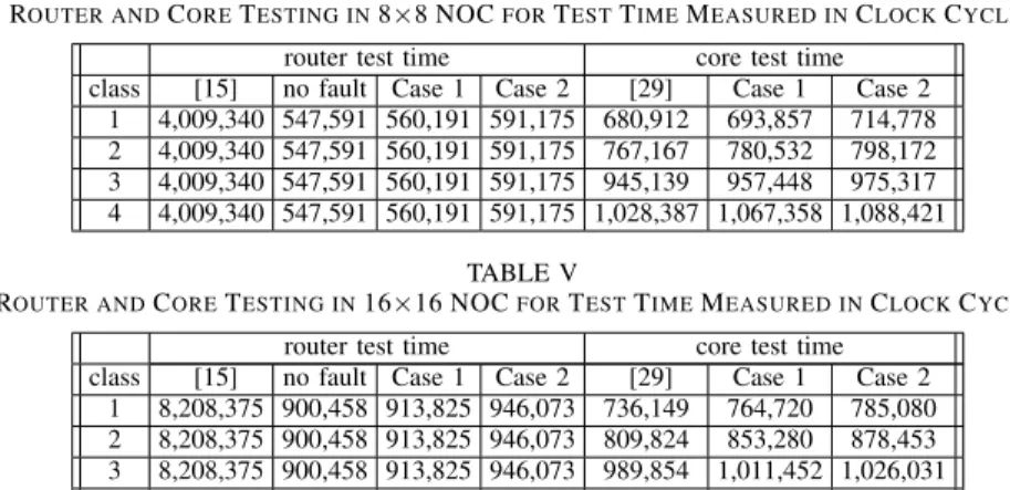
Table III, Table IV, and Table V present experimental results for 6×6, 8×8, and 16×16 mesh-based NOCs, respectively. Table III presents the test time for router and core testing in 6×6 meshes. The column router test time presents router test time comparison of the proposed method with [15], while the column core test time presents the core test time comparison of the proposed method with [29].
As shown in Table III, the test time for core testing in both Case 1 and Case 2 is a little higher than that in a fault-free NOC based on the method in [29] because of the new fault-tolerant routing scheme. The test time increases only slightly when the number of link and router failures increases. Therefore, router and and link failures do not have a significant impact on the test-delivery time for core testing.
Router test time for the new method is much less than for in [15], even though [15] provided hardware support for multicast. The most important reasons are: (1) the new method
provides a scheme in which test delivery and test application can proceed concurrently, but the method in [15] handles test delivery and test application sequentially; (2) the scan-tree architecture is used in our work, while the results in [15] are obtained using scan chains with the same number of scan-in pins.
Table IV presents experimental results for faulty8×8 meshes when three link and one router failures are randomly injected in Case 1, and four link and two router failures are randomly injected in Case 2. The proposed router testing method can reduce test cost significantly compared to [15]. Increase in the network size leads to significant test-cost increase for both in [15] and the new method. However, the core testing time based on the new method remains almost the same. Table V presents results for 16 × 16 meshes. The core testing time for the previous method in [15] is almost doubled compared to that for the network 8 × 8. The core testing time for the proposed method increases by small amount.
VI. CONCLUSIONS
We have presented a unified approach to test a network-on-chip in entirety. The proposed scheme detects link failures, router faults, and faults in cores in a single flow. Routers with the same degree (i.e., the same number of routers that is connected to it) are deemed to be identical from a test perspective. Test packets for the routers are delivered in the faulty network via the IFFRs and IFFLs, whereby identical routers can share the same test packets.
The test packets of cores are delivered along fault-free routers and links after all faulty routers have been identified by using a new fault-tolerant multicast algorithm. The proposed fault-tolerant multicast algorithm does not require any changes to the router architecture. Hence, unlike in prior work, this method does not constrain test-packet delivery within the tested sub-network. Experimental results highlight the effectiveness of the proposed method in reducing test time. Small delay defect
TABLE IV
ROUTER ANDCORETESTING IN8×8 NOCFORTESTTIMEMEASURED INCLOCKCYCLES router test time core test time
class [15] no fault Case 1 Case 2 [29] Case 1 Case 2 1 4,009,340 547,591 560,191 591,175 680,912 693,857 714,778 2 4,009,340 547,591 560,191 591,175 767,167 780,532 798,172 3 4,009,340 547,591 560,191 591,175 945,139 957,448 975,317 4 4,009,340 547,591 560,191 591,175 1,028,387 1,067,358 1,088,421
TABLE V
ROUTER ANDCORETESTING IN16×16 NOCFORTESTTIMEMEASURED INCLOCKCYCLES router test time core test time
class [15] no fault Case 1 Case 2 [29] Case 1 Case 2 1 8,208,375 900,458 913,825 946,073 736,149 764,720 785,080 2 8,208,375 900,458 913,825 946,073 809,824 853,280 878,453 3 8,208,375 900,458 913,825 946,073 989,854 1,011,452 1,026,031 4 8,208,375 900,458 913,825 946,073 1,074,258 1,092,421 1,148,236
or transition fault testing for router/core of NOCs are further work of this paper [4]–[6], [33].
REFERENCES
[1] M. Agrawal, M. Richter, and K. Chakrabarty, “A dynamic programming solution for optimizing test delivery in multicore SOCs,” in Proc. of Int. Test Conference, paper 1.3, Oct. 2012.
[2] C. Aktouf, C. Robach, and A. Marinescu, “A routing testing of a VLSI massively parallel machine based on IEEE 1149.1,” in Proc. of IEEE Int. Test Conference, pp. 781-788, 1995.
[3] L. Benini and G. DeMicheli, “Networks on chips: A new SOC paradigm,” IEEE Computer, vol. 35, no. 1, 2002.
[4] Z. Chen and D. Xiang, “The ATPG conflict-driven scheme for high transition fault coverage and low test cost,” in Proc. of VLSI Test Symp., pp. 146-151, 2009.
[5] Z. Chen and D. Xiang, “Low-capture-power at-speed testing using partial launch-on-capture test scheme,” in Proc. of VLSI Test Symp., pp. 141-146, May 2010.
[6] Z. Chen, K. Chakrabarty, and D. Xiang, “MVP: Capture-power reduction with minimum-violations partitioning for delay testing,” in Proc. of Int. Conf. on Computer-Aided Design, pp. 149-154, Nov. 2010.
[7] E. Cota, L. Carro, F. Wagner, and M. Lubaszewski, “Power-aware NOC reuse on the testing of core-based systems,” in Proc. Int. Test Conference, paper 24.2, pp. 612-621, 2003.
[8] E. Cota, F. L. Kastensmidt, M. Cassel, P. Meirelles, A. Amory, and M. Lubaszewski,“Redefining and testing interconnect faults in mesh NOCs,” in Proc. IEEE Int. Test Conf., 2007.
[9] E. Cota and C. Liu, “Constraint-driven test scheduling for NOC-based Systems,” IEEE Trans. on Computer-Aided Design, vol. 25, no. 11, pp. 2465-2478, 2006.
[10] W. J. Dally and B. Towles, “Route packets not wires: On-chip interconnection networks,” in Proc. of Design Automation Conference, June 2001.
[11] J. Dalmasso, E. Cota, M. L. Flottes, and B. Rouzeyre, “Improving the test of NOC-based SOCs with help of compression schemes,” in Proc. of Annual Symp. on VLSI, pp. 139-144, 2008.
[12] G. DeMicheli and L. Benini, Networks on Chips, Morgan Kaufmann Publishers, 2006.
[13] J. Duato, S. Yalamanchili, and L. Ni, Interconnection Networks: An Engineering Approach, IEEE Press, 1997.
[14] V. Froese, R. Ibers, and S. Hellebrand, “Reusing NOC-infrastructure for test data compression,” in Proc. of IEEE 28th VLSI Test Symposium, pp. 227-231, May 2010.
[15] C. Grecu, A. Ivanov, R. Saleh, and P. P. Pande, “Testing network-on-chip communication fabrics,” IEEE Trans. on Computer-Aided Design, vol. 26, no. 12, pp. 2201-2214, 2007.
[16] M. R. Kakoee, V. Bertacco, and L. Benini, “A Distributed and Topology-Agnostic Approach for On-line NoC Testing,” in Proc. of Int. Symp. On Networks-on-Chip, pp. 113-120, 2011.
[17] D. Kohler and M. Radetzki, “Fault-Tolerant Architecture and Deflection Routing for Degradable NoC Switches,” in Proc. of Int. Symp. On networks-on-Chip, pp. 22-312009.
[18] D. H. Linder and J. C. Harden, “An adaptive and fault-tolerant wormhole routing strategy for k-ary n-cube,” IEEE Trans. Computers, vol. 40, no. 1, pp. 2-12, Jan. 1991.
[19] C. Liu and V. Iyengar, “Test scheduling with thermal optimization for network-on-chip systems using variable rate on-chip clocking,” in Proc. of DATE, 2006.
[20] P. K. McKinley, H. Xu, A. H. Hossein, and L. M. Ni, “Unicast-based multicast communication in wormhole-routed networks,” IEEE Trans. Parallel and Distributed Systems, vol. 5, no. 12, pp. 1252-1265, 1994. [21] D. K. Panda, S. Singal, and R. Kesavan, “Multidestination message passing
in wormhole k-ary n-cube networks with base routing conformed paths,” IEEE Trans. Parallel and Distributed Systems, vol. 10, no. 1, pp. 76-96, 1999.
[22] K. Peterson and K. Oberg, “Toward a scalable test methodology for 2D-mesh network-on-chips,” in Proc. of Design Automation, and Test in Europe, 2007.
[23] M. Radetzki, C. Feng, X. Zhao, and A. Jansch, “Methods for Fault Tolerance in Networks-on-Chip,” ACM Computing Surveys, vol. 46, no. 1, Article 8, Oct. 2013.
[24] A. Ramdas and O. Sinanoglu, “Testing chips with spare identical cores,” IEEE Trans. on Computer-Aided Design, vol. 32, no. 7, pp. 1124-1135, July 2013.
[25] L. Seiler, et al., “Larrabee: A many core X86 architecture for visual computing,” ACM Trans. on Graphics, Proc. of ACM SIGGRAPH, vol. 27, no. 3, article 18, 2008.
[26] S. Shamshiri, A. Ghofrani, and K. -T. Cheng, “End-to-end error correction and online diagnosis for on-chip networks,” in Proc. of Int. Test Conference, paper 10.3, Sept. 2011.
[27] X. T. Tran, Y. Thonart, J. Durupt, V. Beroulle, and C. Robach,
“A design-for-test implementation of an asynchronous network-on-chip architecture and its associated test pattern generation and application,” in Proc. of Int. Symp. on Network-on-Chip, pp. 149-158, 2008.
[28] D. Xiang, K. Chakrabarty, and H. Fujiwara, “Multicast-based testing and thermal-aware test scheduling for 3D ICs with a stacked network-on-chip,” IEEE Trans. Computers, vol. 65, no. 9, pp. 2767-2779, Sept. 2016. [29] D. Xiang and Y. Zhang, “Cost-effective power-aware core testing in
NOCs based on a new unicast-based multicast scheme,” IEEE Trans. Computer-Aided Design, vol. 30, no. 1, pp. 135-147, Jan. 2011. [30] D. Xiang, “A Cost-Effective Scheme for Network-on-Chip Router and
Interconnect Testing,” in Proc. of Asian Test Symp., pp. 207-212, Nov. 2013.
[31] D. Xiang, G. Liu, K. Chakrabarty, and H. Fujiwara, “Thermal-aware test scheduling for NOC-based 3D integrated circuits,” in Proc. of 21th IFIP/IEEE Int. Conf. on VLSI-SOC, pp. 99-104, Oct. 2013.
[32] D. Xiang and K. Shen, “A new unicast-based multicast scheme for network-on-chip router and interconnect testing,” ACM Trans. on Design Automation of Electronic Systems, vol. 21, Issue 2, Article 24, Jan. 2016. [33] D. Xiang, J. Li, K. Chakrabarty, and X. Lin, “Test compaction for small-delay defects using an effective path selection scheme,” ACM Trans. on Design Automation of Electronic Systems, Vol. 18, No. 3, Article 44, July 2013.