Motion
Controller
Stand-Alone
Plenty of
axes!
This is
Stand-Alone!
Ideal for
complete machine
control!
Start with
Stand-Alone.
Whatever your system size, Mitsubishi Electric’s
Q170MCPU stand-alone motion controller meets your
needs. The Q170MCPU integrates a power supply, PLC,
and motion controller, is easy to use, and features
improved motion control and flexible expandability. To
obtain maximum effect with minimum investment,
manage total machine control with the stand-alone
motion controller!
Mitsubishi Electric’s Q170MCPU meets your needs.
Got it!
For total machine
control use
Stand-Alone!
Compact
Even useful
for integrating
equipment into
the manufacturing
line.
The high
performance
of iQ Platform!
More than
enough axes
for total machine
control!
Simple!
Power supply, PLC,
motion controller;
all integrated
into a single,
compact unit!
This is Stand-Alone!
3
9
Solutions
Specifications
Information
01
System configuration
CPU specifications
System configuration / Software
Dimension drawings
GLOBAL FA CENTERS
About warrantee
10
11
12
13
14
Three-in-one: Power supply, PLC, and Motion
Controller.
Empowered! No more model
selection worries!
4
02
Better space-saving when combined with a
2-axes-in-1 servo amplifier.
Empowered! Panel and
equipment size can be educed!
5
03
Compatible with MELSEC-Q Series modules.
Empowered! Flexible expansion
for any control purpose!
6
04
The high-speed control of iQ Platform.
Empowered! Dramatic increases
in productivity!
7
05
Easy parameter setting.
Empowered! Speedy startup!
Effortless debugging!
8
06
Use program resources efficiently.
01
solution
02
solution
S t a n d - A l o n eM o t i o n C o n t ro l l e r4 3
Three-in-one: Power supply, PLC, and Motion Controller.
No more
model selection worries!
Empower
ed!
The compact Q170MCPU integrates a power supply,
PLC, and motion controller and features built-in
incremental synchronous encoder and mark
detection signal interfaces needed for the
packaging equipment industry and others. No need
to worry over which model to choose – this unit
provides it all!
Easily introduce a controller
into your machine.
A good choice even if
the number of servo axes
increases later!
Which PLC do I choose? Future number of
servo axes? Which options units? Which power
supply? The integrated Q170MCPU solves all of
these questions at once.
The Q170MCPU can accommodate up to 16 axes.
Furthermore, the Q170MCPU makes switching
pneumatic cylinders and stepping motors to
higher performing servos an easy task.
Total machine control, fitting even for machines with only eight-axes.
Select Stand-Alone for worry-free model selection.
C a s e
S t u d y
No need for additional
registration mark sensors!
The Q170MCPU has built-in inputs for
an INC synchronous encoder and up to
4 registration mark sensors. It can be
used for packaging equipment without
adding extra I/O modules.
Introduce
servo
technology
quickly
with ease!
Simple unit
with
three functions
Better space-saving when combined with a 2-axes-in-1 servo amplifier.
Panel and equipment size
can be reduced!
Empower
ed!
The Q170MCPU is a compact 52 × 178 × 135 mm.
Combining the controller with Mitsubishi’s 2-in-1 MR-J3W
servo amplifier saves even more space.
Even in a jam-packed panel, the Stand-alone controller
makes space-saving design possible.
Just like this,
you can squeeze
everything into
a packed panel!
Save even more space
by combining with
the 2-in-1 servo amplifier!
Synergistic
space-saving!
The 2-in-1 MR-J3W servo amplifier has
the same shape and installation area as
the Q170MCPU. When comparing
against two MR-J3 amps, the J3W can
be installed in 25% less space.
Combined with the Q170MCPU, an
optimum space-saving solution can be
realized. Additionally, the 2-slot
expansion base is just 106 mm × 98 mm,
allowing limited panel and equipment
space to be used effectively.
At least an 8-slot base is needed... Q170MCPU! A single, simple design!
One Stand-alone,
two J3W’s and a 2-slot expansion base. Done! A lot of space taken up by empty slots
and additional amplifier units. Power
supply PLCCPU Motion CPU
Q170MCPU Q170MCPU 2-in-1
MR-J3W servo amplifier
24 VDC power supply
24 VDC power supply
30 mm 10 mm
The controller and servo amplifier share
the same dimensions!
C a s e
S t u d y
98 mm
106 mm
INC synchronous
encoder
Mark sensor
Compatible with MELSEC-Q Series modules.
Flexible expansion
for any control purpose!
Empower
ed!
Select from over 100 different types of Mitsubishi
MELSEC-Q Series units and install directly into the
Q170MCPU expansion base – no power supply
needed.
Flexible system expansion is an important
Q170MCPU advantage.
From expanded I/O, A/D conversion, and
temperature control to additional network
communication units and more. All can be
added quickly and easily. No need to
redesign the system when adding or
changing functions!
The open CC-Link IE controller
network can be used to develop large
scale systems with ease.
No need to do a system redesign every time you want
to add or change functions!
Over 100 different types
of modules for flexible expansion of functions!
Even constructing large
systems is incredibly easy!
The high-speed control of iQ Platform.
Dramatic increases
in productivity!
Empower
ed!
Despite being compact, the Q170MCPU
contains the same high performance as
Mitsubishi’s industry leading iQ Platform
controllers. All this performance, yet the
stand-alone
Q170MCPU motion
controller is still
easy to use.
High speed and high performance in a small package.
Delivering the power to reduce tact time and raise productivity!
Equipped with a high-speed multi-CPU bus,
worry not when increasing the number
of servo axes!
Unit selection
freedom!
Amazing
performance!
Wide selection of MELSEC-Q Series modules
The limitless Q170MCPU!
[Increased in-position response speed]
Q170MCPU
QH motion
In-position response
time Short Long
Two times as fast!
The Q170MCPU uses the same high-speed
multi-CPU communication as iQ Platform. With
this, high-speed 0.88 ms data transfer of up to
14kW is made possible between the PLC and
motion CPU. High level iQ Platform motion
control is made possible without any
degradation in performance even in systems
with large PLC programs and scan times.
Measurements
In-position response time In-position
signal
Time Motor speed
Fundamental motion performance
(number of axes that can be controlled at 0.44ms motion CPU cycle time) *With SV13 OS
Q170MCPU
QH motion
Q170MCPU
QH motion
Performance
SFC motion processing time *When D800L = D802L + D804L
Processing time
Two times improvement!
1
0 2 3 4 5 6 7 8 9
1
0 2 3 4 5 6 7 8 9 10 11 12 Four-fold speed increase
11.75µs
C a s e
S t u d y
Machine A Machine B Machine C Supervisory PLC
Machine D Machine E
C a s e
S t u d y
High-speed multi-CPU bus
PLC CPU
Multi-CPU high-speed communication shared memory
Sequence control processor
Device memory
Motion CPU
Multi-CPU high-speed communication shared memory
Motion control processor
Device memory
2.34µs
6 axes 3 axes
05
solution
06
solution
S t a n d - A l o n eM o t i o n C o n t ro l l e r8 7
Easy parameter setting.
Speedy startup!
Effortless debugging!
Empower
ed!
In other multi-CPU platforms, lots of configuration must
be done before the Motion CPU and PLC CPU can
communicate properly. This can result in hours of
wasted time for the engineers involved. The Q170MCPU
changes the game by seamlessly integrating sequence
and motion. Thus, setup is quick and easy without any
added steps for multi-CPU settings.
Use program resources efficiently.
System expansion
with minimum design costs!
Empower
ed!
Can a stand-alone motion controller handle
future system expansion?
With the Q170MCPU, your doubts are
erased. Move to the high-end iQ Platform
motion controller with minimum design
hours and costs.
Integrating individual machines into a line soon?
Simplify future expansion by easily upgrading the controller!
C a s e
S t u d y
Setting up multiple CPU’s used to be hard work.
Now, start a new project, go into RUN mode. It’s that easy!
Start the CPU in one-shot!
Sample data assists startup!
Software for the Q170MCPU comes
with sample project data that
pre-configures multi-CPU settings
and gives the user additional
benefits such as automatically
adding labels to motion specific
devices when used in PLC ladder.
Two PCs can be connected at the
same time, allowing for multiple
engineers to simultaneously debug
sequence programs and debug
motion programs/perform gain
adjustment. (Of course, one PC can
do everything as well.)
For example, a machine built with the
Q170MCPU can be extended quite easily.
The Q170MCPU’s project files can be directly
used with the iQ Platform’s Q173DCPU.
Flexibly integrate machines
into your assembly line!
Debugging time reduced
by using two personal
computers!
Easy to run!
Simple setup
using sample
data!
Initial introduction
With such system expansion,Editing of sequence programs Editing of motion programs Gain adjustment
USB
Ethernet Q170MCPU
easily upgrade to Q173DCPU!
When further system
expansion is required,
The same
MELSOFT
MT Works2
engineering tool!
C a s e
S t u d y
Pre-processing by company A
Your company’s equipment
Post-processing by company B
pre- and post-processing are completely integrated into your company’s production line.
The programs,
extension modules,
Servo motor Servo amplifier
MR-J3- B
2-in-1 servo amplifier
MR-J3W- B USB
Motion controller
Q170MCPU
PERIPHERAL I/F (Ethernet)
MELSOFT MT Works2
RS-232
Servo motor
Linear servo motor
MELSOFT engineering
environment
PLC programming software GX Developer
SW8D5C-GPPW-E ver. 8.76E or newer (CD-ROM)
Motion controller engineering environment
MELSOFT MT Works2 SW1DNC-MTW2-E ver. 1.05F or newer (CD-ROM)
Servo setup software MR Configurator MRZJW3-SETUP221E ver. C2 or newer (CD-ROM)
Arc interpolation, constant-speed control, indexing, fixed-position stop speed control, speed switching control, speed control, speed position switching, linear interpolation -- 1 to 4 axes
Mechanical support language Dedicated language
Synchronous control, electronic shaft, electronic clutch, electronic cam, draw control
Motion OS software CD-ROM
For transfer and assembly SV13 for motion SFC
Machine automation SV22 for motion SFC
* Only MELSEC-Q Series memory cards are compatible
* When configuring, check that total 5-VDC current for all units is under the allowable value of 4[A]. (Including the 2[A] current consumed by the Q170MCPU.)
Expansion cable QC B
Manual pulse generator MR-HDP01 * For MT Works2 ver. 1.06G or newer
INC Synchronous encoder
* For MT Works2 ver. 1.06G or newer
Graphic operation terminal (GOT)
* Connectable through RS-232 but not Ethernet Q5 B expansion base (up to 1 level) No power supply needed
SW8DNC-SV13QG SW8DNC-SV22QF
External servo signals (FLS, RLS, DOG) · Electronic component
assembly · Inserter · Feeder · Molding machine · Transfer equipment · Painting machine
· Press feeder · Food processing · Food packaging · Winder · Spinner · Loom · Chip mounter
· Wafer slicer · Loader and unloader · Bonding machine · X-Y table
· Knitter · Printer · Bookmaker · Tire former · Paper-maker
* For MT Works2 ver. 1.06G or newer
Motion OS software package
Emergency stop input (24 VDC) Memory card 24 VDC power supply
General input signal /
mark detection input signal: 4 points General output signal: 2 points SSCNET
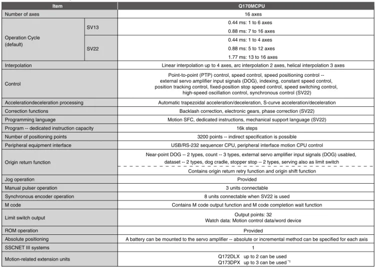
Interpolation
0.44 ms: 1 to 4 axes 0.88 ms: 5 to 12 axes 1.77 ms: 13 to 16 axes
Linear interpolation up to 4 axes, arc interpolation 2 axes, helical interpolation 3 axes
Output points: 32
Watch data: Motion control data/word device Provided
A battery can be mounted to the servo amplifier -- absolute or incremental method can be specified for each axis Point-to-point (PTP) control, speed control, speed positioning control --
external servo amplifier input signals (DOG), indexing, constant speed control, position tracking control, fixed-position stop speed control, speed switching control,
high-speed oscillation control, synchronous control (SV22)
Q172DLX up to 2 can be used Q173DPX up to 3 can be used *1
SV13
SV22
Control
*1: Three units are possible when using an INC synchronous encoder with SV22. When a manual pulse generator is connected, only 1 can be used. Near-point DOG -- 2 types, count -- 3 types, external servo amplifier input signals (DOG) usabled,
dataset -- 2 types, dog cradle, stopper stop -- 2 types, serving also as limit switch
1 Operation Cycle
(default)
0.44 ms: 1 to 6 axes 0.88 ms: 7 to 16 axes
Contains origin return retry function and origin shift function Accelerationdeceleration processing
Correction functions Programming language
Program -- dedicated instruction capacity Number of positioning points
Peripheral equipment interface
Origin return function
Jog operation Manual pulser operation Synchronous encoder operation M code
Limit switch output ROM operation Absolute positioning SSCNET III systems Motion-related extension units
Automatic trapezoidal acceleration/deceleration, S-curve acceleration/deceleration Backlash correction, electronic gears, phase correction (SV22) Motion SFC, dedicated instructions, mechanical support language (SV22)
16k steps
3200 points -- indirect specification is possible
USB/RS-232 sequencer CPU, peripheral interface motion CPU control
Provided 3 units connectable 8 units connectable when SV22 is used
Contains M code output function and M code completion wait function
PLC CPU Control method
Input/output control method
Equivalent to Q03UDCPU (20k steps) Stored program cyclic operation
Refresh method 0.02µs 0.04µs 28 0.12µs 858 Possible Possible Possible
0.5 to 2000 ms --set in 0.5 ms units 20k steps (80k bytes)
8k bytes 32k bytes 8192 points 512 points Item Specifications Processing speed -- sequence instructions LD instruction MOV instruction
PC MIX value (instruction / µs) Floating-point addition Total instructions
Real number -- floating-point -- operation instruction Character string processing instruction
PID instruction
Constant scanning Program capacity
Shared CPU memory
Input/output device points (X/Y) Input/output points (X/Y) *1
Relay symbol language (ladder), Logic sybolic language (list), MELSAP3 (SFC), MELSAP-L, Structured text (ST)
Standard QCPU area
*1: Up to 320 input/output unit points can be used (64 points × 5 units).
PLC control specifications
PLC control language –
(language dedicated to PLC control)
Possible Special function instruction -- trigonometric,
square root, exponential operation, etc.
M o t i o n C o n t ro l l e r S t a n d - A l o n e
System configuration
Dimension drawings
12 11
Software
CE, UL CE, UL — *1: Be sure to order the emergency stop input cable. Emergency stop cannot be canceled without this cable.*2: Cable fabrication requires special tools. We do not supply special tools. Please obtain independently.
*1: shows cable length. (05: 0.45 m, 06: 0.6 m, 12: 1.2 m, 30: 3 m, 50: 5 m, 100: 10 m)
Usage Model
SW8DNC-SV13QG SW8DNC-SV22QF For transfer and assembly (SV13)
For automatic equipment (SV22) Expansion base unit Q52B
Q55B QC B
2-I/O slot not requiring power supply 5-I/O slot not requiring power supply
Length: 0.45 m, 0.6 m, 1.2 m, 3 m, 5 m, and 10 m Expansion cable *1
Version 1.05F or newer Support main OS software SV13 for transfer and assembly SV22 for automatic equipment
Product Model Applicable version
SW1DNC-MTW2-E SW1DNC-MTW2-EAZ (Additional license: 1) Motion controller engineering environment
MELSOFT MT Works2
Version 8.76E and after SW8D5C-GPPW-E
PLC programming software GX Developer
Version C2 and after
Motion controller Q170MCPU
Expansion base Q5 B
<Installation>
External servo signal input Q172DLX
Manual pulse input Q173DPX
135 168 161 4.6 52 178 52 154 7 6 7 8 38 [Unit: mm] 27.4 23 4 90 98 Q172DLX Q172DLX CTRL [Unit: mm] 27.4 23 4 98 90 Q173DPX Q173DPX 1 2 3 PLS.A 1 2 3 PLS.B 1 2 3 TREN PULSER 6 1 2 3 4 5 ON Panel Indicates location of panel ceiling or wiring duct.
Door
135 mm
100 mm Motion
controller *1 Servo
amplifier 40 mm or more
90 mm
or more 5 mm or more*1 5 mm or more
30 mm or more 30 mm
or more
10 mm or more
Indicates location of panel ceiling or wiring duct.
Panel
Base unit
4 mounting screws (M4×14)
W H IN Ws1 Hs 1 Hs 2 Ws2
I/O0 I/O1 I/O2 I/O3 I/O4
OUT
*1: Install the motion controller to the left of the servo amplifier.
*1: 20 mm or more when the expansion cable is connected without the adjacent unit removed. *2: 80 mm or more when a connector is used.
*3: When the wiring duct is 50 mm or less high. In other cases, the distance must be 40 mm or more. 98 mm
20 mm or more*2
30 mm or more*3
30 mm or more
Motion controller
Base unit
*3: shows cable length. (015: 0.15 m, 03: 0.3 m, 05: 0.5 m, 1: 1 m, 2: 2 m, 3: 3 m, 5: 5 m, 10: 10 m, 20: 20 m, 30: 30 m, 40: 40 m, 50: 50 m) *4: Check with Mitsubishi Electric regarding cables less than 30 m long.
Manufacturer Tools used Crimping tool: 57026-5000 for UL1007 57027-5000 for UL1015
Removal tool: 57031-6000 Molex
Tyco Electronics AMP Connector for emergency stop
input cable
Removal tool:1762846-1 24 VDC power connector
IN OUT [Unit: mm] USB POWER STOP RESET RUN P E R IP H E R A L I/ F CN1 EXT.IO 24VDC OUT FRONT C A R D RS-232 EMI EJECT MITSUBISHI Q170MCPU MODE RUN ERR. USER BAT. BOOT PULL PUSH USB POWER STOP RESET RUN P E R IP H E R A L I/ F CN1 EXT.IO 24VDC OUT FRONT C A R D RS-232 EMI EJECT MITSUBISHI Q170MCPU MODE RUN ERR. USER BAT. BOOT PULL 189 167±0.3 15.5 98 7 80±0.3 W Ws1 Ws2 H Hs1 Hs2 [Unit: mm] Q52B 106 83.5±0.3 Q55B
Motion-specific units
Devices used in common with MELSEC Q Series PLC
Motion OS software
Engineering environment
Product Model Applicable version
Product Model Applicable version
MRZJW3-SETUP221E Servo setup software
MR Configurator
Product Model Description
Applicable overseas
standard
Door
Product Model Description
Applicable overseas
standard
Q170MCPU
Integrated with power supply, PLC CPU, and motion CPU
With battery (Q6BAT), built-in interface connector, 24 VDC power supply connector, and emergency stop input cable connector
Control of up to 16 axes, operation of 0.44 ms or more, built-in interface for INC synchronous encoder: 1 channel, general input signal/mark detection input signal: 4 points, general output signal: 2 points
Emergency stop input
-- order cables together with the motion controller.
Connector for emergency stop input cable provided with Q170MCPU
CE, UL — — — — — — — — — — — — — CE, UL CE, UL — — — — — — Motion controller
Emergency stop input cable *1
Connector for emergency stop input cable *2
SSCNET cable *3
External servo signal input unit Manual pulse input unit Built-in interface connector set 24 VDC power supply connector set *2
24 VDC power cable
Large-capacity battery holder Manual pulse generator
• Q170MCPU MR-J3(W)- B
• MR-J3(W)- B MR-J3(W)- B
External servo signal input for 8 axes (FLS, RLS, STOP, DOG/CHANGE × 8)
Interface for manual pulse generator MR-HDP01/INC synchronous encoder × 3, 3 tracking input points
Connector for INC synchronous encoder/mark detection signal interface connection provided with Q170MCPU
24 VDC power supply connector provided with Q170MCPU 24 VDC 2-meter power cable with crimp terminal R1.25-3.5
24 VDC power cable with 2-meter EMI terminal with crimp terminal R1.25-3.5
Cable for disabling the emergency stop input on the front of the Q170MCPU by short-circuiting the EMI terminal to the 24 VDC power supply
Battery holder for Q7BAT provided with Q7BAT
Pulse resolution: 25 PLS/rev -- 100 PLS/rev after magnification by 4 Allowable speed: 200 r/min in normal rotation Voltage output Allowable load Radial load: 19.6 N Thrust load: 9.8 N Q170DEMICBL05M Q170DEMICBL1M Q170DEMICBL3M Q170DEMICBL5M Q170DEMICBL10M Q170DEMICBL15M Q170DEMICBL20M Q170DEMICBL25M Q170DEMICBL30M Q170DEMICON MR-J3BUS M MR-J3BUS M-A MR-J3BUS M-B*4
Q172DLX Q173DPX Q170MIOCON Q170MPWCON Q170MPWCBL2M Q170MPWCBL2M-E Q170MBAT-SET MR-HDP01
Nominal current capacity: 1800 mAh 0.5 m 1 m 3 m 5 m 10 m 15 m 20 m 25 m 30 m
Nominal current capacity: 5000 mAh
— — For retaining SRAM memory data in motion controller
-- programs, parameters, absolute position data, and latch data
Standard cord for inside a panel: 0.15 m, 0.3 m, 0.5 m, 1 m, 3 m Standard cable for outside a panel: 5 m, 10 m, 20 m
Long-distance cable: 30 m, 40 m, 50 m
Q6BAT Battery
Before using the Product, please check our product warrantee conditions below.
1. Period and scope of warrantee
Should a defect or a failure (hereafter referred to as “failure”) occurs with the Product due to a reason or a cause attributable to Mitsubishi Electric Corporation (the Manufacturer), the Manufacturer will repair the Product free of charge through your local dealer or supplier.
Should Manufacturer’s service engineer need to travel to the site for repair within Japan or overseas, however, the Purchaser shall bear the actual travel expenses. The scope of warrantee shall not cover any readjustment or test operation at the site in relation to replacing the failed Product.
[Warrantee period]
The Manufacturer warrants the Product against a defect or a failure of the Product attributable to the Manufacturer for 36 months from the date of purchase or the date of Product delivery at the purchaser designated site.
Assuming the maximum logistics and/or retail period of six months after shipping the Product from the Manufacturer, the warrantee period shall not exceed 42 months. The warrantee period of the repaired Product shall not be extended beyond the warrantee period of the Product before repair.
[Scope of warrantee]
(1) Unless specified or agreed otherwise, the Purchaser is responsible for the primary failure diagnosis.
The Manufacturer or Manufacturer’s service representative or agent may perform the primary failure diagnosis for the Purchaser on a separate contract basis if so requested.
However, the primary failure diagnosis shall be free of charge should the defect or failure so revealed be attributable to the Manufacturer.
(2) The Manufacturer warrants the Product only if the Product is used correctly and properly under the normal operating conditions and environment in accordance with the conditions, precautions and instructions specified in such means as the operation manual, user’s manual and caution labels affixed to the Product.
(3) The Manufacturer’s warrantee shall not apply in the following events. [1] The failure of the Product is attributable to the Purchaser such as
incorrect, inadequate or improper storage, handling and operation or to the Purchaser’s hardware or software design; [2] The failure is caused by any modification to the Product by the
Purchaser without Manufacturer’s prior consent;
[3] Where the Product is incorporated into Purchaser’s equipment, the failure of the Product is considered to have been avoidable if the Purchaser’s equipment was equipped with the regulatory safety devices or with the functions and/or structures considered to be necessary according to the industry’s normal practice; [4] The failure of the Product is considered to have been avoidable if
the consumable items specified in the operation manual and other documents were maintained or replaced normally and properly;
[5] Replacement of consumables such as the battery and fan; [6] Any failure of the product due to external causes such as a fire
and abnormal power supply or to events beyond control such as natural disasters including an earthquake, lightening, storm or flood;
[7] Any failure that is unforeseeable by the technical or scientific level of industry at the time of the product delivery, and; [8] Any failure due to a cause for which the Manufacturer is not held
responsible or the Purchaser acknowledges as such.
2. Repair service availability after cease of production
(1) The Manufacturer may accept the Product for repair on a separate contract basis within seven years after the date when the Manufacturer ceases to produce this particular product. The Manufacturer may announce the cease of production through Manufacturer’s sales or service representatives.
(2) The Manufacturer does not provide any parts or spare parts for the Product after the cease of production.
3. Repair services outside Japan
Contact your local FA Center of the Manufacturer for product repair. Repair conditions may differ from one FA Center to another.
4. The Manufacturer is not liable for any loss of
opportunity or consequential damage.
Regardless of the period or scope of warrantee, the Manufacturer shall in no event be liable for or warrant the Product as to any failure due to a cause not attributable to the Manufacturer, any loss of opportunity or profit to the Purchaser due to failure of the Product of the Manufacturer, any damage, consequential damage, compensation for accident, damage to any product or items other than the Manufacturer’s Product regardless of whether foreseeable or not by the Manufacturer, or any replacement by the Purchaser, readjustment or retesting or the like of Purchaser’s machines or equipment at the site.
5. Changes in Product specifications
The specifications or technical data specified in the product catalogs, manuals or technical documents may be subject to change without prior notice.
6. Application of Product
(1) The Manufacturer’s motion controller shall be used or applied on the condition that any failure or defect of the motion controller will not lead to a serious, critical or fatal accident and that a system of backup or fail-safe functions is provided by the Purchaser outside the equipment and the system works in the event of any failure or defect of the motion controller.
(2) The Manufacturer’s Motion Controllers are for general purposes and designed and manufactured for use in general industry. The Motion Controllers therefore shall not be used for any purposes or applications such as a nuclear power plant or other power plant of an electric company in which a failure may greatly affect the public interest, or any purposes or applications such as for railway companies or public offices where a special quality assurance system is required.
The Motion Controllers shall not be used for any purposes or applications such as for aviation equipment, medical equipment, railway equipment, fuel or combustion equipment, manned transfer equipment, amusement machines and safety equipment in which a failure is expected to greatly affect human lives or properties
For such use or application described above however, the Motion Controllers may be available if the Purchaser agrees that the Products are used or applied within a specific limit and no special quality is required. Consult the representatives of the
Manufacturer.
About warrantee
EUROPEAN FA CENTER
CENTRAL AND EASTERN EUROPE FA CENTER RUSSIAN FA CENTER
UK FA CENTER
KOREAN FA CENTER
BEIJING FA CENTER TIANJON FA CENTER
NORTH AMERICAN FA CENTER
ASEAN FA CENTER THAILAND FA CENTER
Mitsubishi Electric Corp
TAIWAN FA CENTER SHANGHAI FA CENTER
GUANGZHOU FA CENTER
HONG KONG FA CENTER
SHANGHAI FA CENTER
•
MITSUBISHI ELECTRIC AUTOMATION (SHANGHAI) LTD.
80 Xin Chang Road, 4th Floor,
Shanghai Intelligence Fortune Leisure Plaza
Huang Pu district, Shanghai 200003, China
Tel : 86-21-6121-2460 Fax : 86-21-6121-2424
BEIJING FA CENTER
•
MITSUBISHI ELECTRIC AUTOMATION (SHANGHAI) LTD.
BEIJING OFFICE
Unit 917/918, 9/F Office Tower 1,
Henderson Center, 18 Jianguomennei Dajie,
Dongcheng District, Beijing 100005, China
Tel : 86-10-6518-8830 Fax : 86-10-6518-8030
TIANJON FA CENTER
•
MITSUBISHI ELECTRIC AUTOMATION (SHANGHAI) LTD.
TIANJIN OFFICE
B-2 801/802 Youyi Building,
No.50 Youyi Road, Hexi District,
Tianjin 300061, China
Tel : 86-22-2813-1015 Fax : 86-22-2813-1017
GUANGZHOU FA CENTER
•
MITSUBISHI ELECTRIC AUTOMATION (SHANGHAI) LTD.
GUANGZHOU OFFICE
Rm.1609, North Tower, The Hub Center, No.1068,
Xing Gang East Road, Haizhu District, Guangzhou 510335, China
Tel : 86-20-8923-6713 Fax : 86-20-8923-6715
HONG KONG FA CENTER
•
MITSUBISHI ELECTRIC AUTOMATION (HONG KONG) LTD. (FA DIVISION)
10th Floor, Manulife Tower, 169 Electric Road,
North Point, Hong Kong
Tel : 852-2887-8870 Fax : 852-2887-7984
TAIWAN FA CENTER
•
SETSUYO ENTERPRISE CO., LTD.
6F No.105 Wu Kung 3rd RD, Wu-Ku Hsiang,
Taipei Hsien, Taiwan
Tel : 886-2-2299-2499 Fax : 886-2-2299-2509
KOREAN FA CENTER
•
MITSUBISHI ELECTRIC AUTOMATION KOREA CO., LTD.
THAILAND FA CENTER
•
MITSUBISHI ELECTRIC AUTOMATION THAILAND CO., LTD.
Bang-Chan Industrial Estate No.111
Moo4, Serithai Road, T.kannayao A.kannayao
Bangkok 10230, Thailand
Tel : 66-2906-8255 Fax : 66-2906-3239
ASEAN FA CENTER
•
MITSUBISHI ELECTRIC ASIA PTE, LTD.
307 Alexandra Road #05-01/02
Mitsubishi Electric Building, Singapore 159943
Tel : 65-6470-2480 Fax : 65-6476-7439
NORTH AMERICAN FA CENTER
•
MITSUBISHI ELECTRIC AUTOMATION, INC.
500 Corporate Woods Parkway, Vernon Hills, IL 60061, USA
Tel : 1-847-478-2330 Fax : 1-847-478-2396
EUROPEAN FA CENTER
•
MITSUBISHI ELECTRIC EUROPE B.V. GERMAN BRANCH
Gothaer Strasse 8 D-40880 Ratingen, GERMANY
Tel : 49-2102-486-2630 Fax : 49-2102-486-7170
CENTRAL AND EASTERN EUROPE FA CENTER
•
MITSUBISHI ELECTRIC AUTOMATION EUROPE B.V. CZECH BRANCH
Radlická 714/113a, 15800 Praha 5, Czech Republic
Tel : 420-251-551-470 Fax : 420-251-551-471
UK FA CENTER
•
MITSUBISHI ELECTRIC EUROPE B.V. UK BRANCH
(Customer Technology Centre)
Travellers Lane, Hatfield, Hertfordshire, AL10 8XB, U.K.
Tel : 44-1707-278843 Fax : 44-1707-278992
RUSSIAN FA CENTER
•
MITSUBISHI ELECTRIC EUROPE B.V. RUSSIAN BRANCH
Sverdlovskaya Emb.,44, Bld Sch, BC "Benua";195027,
St.Petersburg, Russia
Mitsubishi Motion Controller
Q Series
L(NA)03050ENG-A 0907(MDOC)
New publication, effective Jul. 2009 Specifications subject to change without notice.